How to Use Arduino UNO R4 WiFi: Examples, Pinouts, and Specs
Introduction
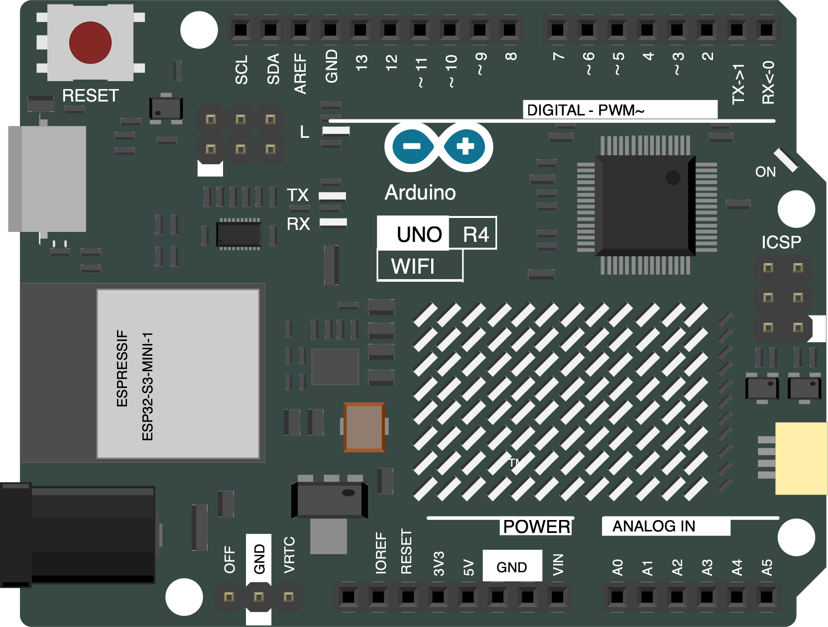
The Arduino UNO R4 WiFi is a versatile microcontroller board that combines the functionality of the traditional Arduino UNO with integrated WiFi capabilities. This board is based on the ATmega328P microcontroller and is designed to facilitate the development of Internet of Things (IoT) projects and wireless applications. It is an ideal choice for hobbyists, educators, and professionals looking to create connected devices with ease.
Explore Projects Built with Arduino UNO R4 WiFi

Explore Projects Built with Arduino UNO R4 WiFi
Common Applications and Use Cases
- Smart home devices
- Wireless sensor networks
- IoT prototypes
- Remote data logging
- Robotics
- Educational projects
Technical Specifications
Key Technical Details
- Microcontroller: ATmega328P
- Operating Voltage: 5V
- Input Voltage (recommended): 7-12V
- Input Voltage (limit): 6-20V
- Digital I/O Pins: 14 (of which 6 provide PWM output)
- Analog Input Pins: 6
- DC Current per I/O Pin: 20 mA
- DC Current for 3.3V Pin: 50 mA
- Flash Memory: 32 KB (ATmega328P) of which 0.5 KB used by bootloader
- SRAM: 2 KB (ATmega328P)
- EEPROM: 1 KB (ATmega328P)
- Clock Speed: 16 MHz
- LED_BUILTIN: Pin 13
- WiFi Module: Integrated (model and specifications may vary)
Pin Configuration and Descriptions
| Pin Number | Function | Description |
|---|---|---|
| 1 | TX | Digital pin for UART transmit |
| 2 | RX | Digital pin for UART receive |
| 3-8 | Digital I/O | General purpose digital input/output pins |
| 9-10 | PWM | PWM output capable pins |
| 11-13 | Digital I/O | General purpose digital input/output pins |
| A0-A5 | Analog Input | Analog input pins |
| AREF | Analog Reference | Reference voltage for the analog inputs |
| GND | Ground | Ground pin |
| RST | Reset | Used to reset the microcontroller |
| 3V3 | 3.3V Supply | 3.3V output from the onboard regulator |
| 5V | 5V Supply | 5V output from the onboard regulator |
| VIN | Voltage Input | Input voltage to the Arduino board |
Usage Instructions
How to Use the Component in a Circuit
Powering the Board:
- Connect a 7-12V power supply to the VIN and GND pins for optimal performance.
- Alternatively, you can power the board via the USB connection.
Connecting to WiFi:
- Utilize the integrated WiFi module to connect to wireless networks.
- Use the appropriate WiFi library in your Arduino sketches to manage connections.
Programming the Board:
- Connect the board to your computer using a USB cable.
- Select "Arduino UNO WiFi" from the Tools > Board menu in the Arduino IDE.
- Write your sketch and upload it to the board using the Arduino IDE.
Important Considerations and Best Practices
- Ensure that the input voltage does not exceed the recommended limits to prevent damage.
- When using WiFi, consider the power consumption and ensure a stable power supply.
- Avoid placing the board in environments with strong electromagnetic interference.
- Use capacitors for decoupling when working with motors or other inductive loads.
Troubleshooting and FAQs
Common Issues Users Might Face
WiFi Connection Issues:
- Ensure the network credentials are correct.
- Check the signal strength and reduce the distance to the router if necessary.
- Restart the board and router to resolve temporary connection issues.
Board Not Recognized by Computer:
- Check the USB cable and try a different port.
- Ensure the correct drivers are installed for the board.
Sketch Upload Failures:
- Verify that the correct board and port are selected in the Arduino IDE.
- Check for errors in the code that may prevent compilation.
Solutions and Tips for Troubleshooting
- Use the onboard LED to test basic sketches and ensure the board is functioning.
- Consult the Arduino forums and community for support on specific issues.
- Update the Arduino IDE and libraries to the latest versions for compatibility.
Example Code for Arduino UNO R4 WiFi
#include <WiFi.h>

// Replace with your network credentials
const char* ssid = "your_SSID";
const char* password = "your_PASSWORD";

void setup() {
  // Initialize serial communication
  Serial.begin(9600);

  // Connect to WiFi
  WiFi.begin(ssid, password);

  // Wait for connection
  while (WiFi.status() != WL_CONNECTED) {
    delay(500);
    Serial.print(".");
  }

  // Print the IP address
  Serial.println("");
  Serial.println("WiFi connected.");
  Serial.print("IP address: ");
  Serial.println(WiFi.localIP());
}

void loop() {
  // Your code here
}
Remember to replace your_SSID and your_PASSWORD with your actual WiFi network credentials. This basic example initializes the WiFi connection and prints the IP address of the Arduino UNO R4 WiFi once connected.