
How to Use SparkFun ITG-3200 Triple-Axis Gyroscope Breakout: Examples, Pinouts, and Specs
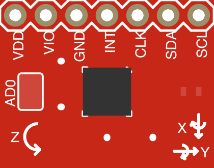
 Design with SparkFun ITG-3200 Triple-Axis Gyroscope Breakout in Cirkit Designer
Introduction
The SparkFun ITG-3200 Triple-Axis Gyroscope Breakout (Part ID: SEN-09801) is a compact and high-performance gyroscope sensor designed to measure angular velocity along three axes (X, Y, and Z). This sensor is ideal for applications requiring precise motion tracking, such as robotics, drones, gaming controllers, and motion-based user interfaces. The ITG-3200 integrates a MEMS gyroscope with a digital I2C interface, making it easy to interface with microcontrollers and other digital systems.
Explore Projects Built with SparkFun ITG-3200 Triple-Axis Gyroscope Breakout
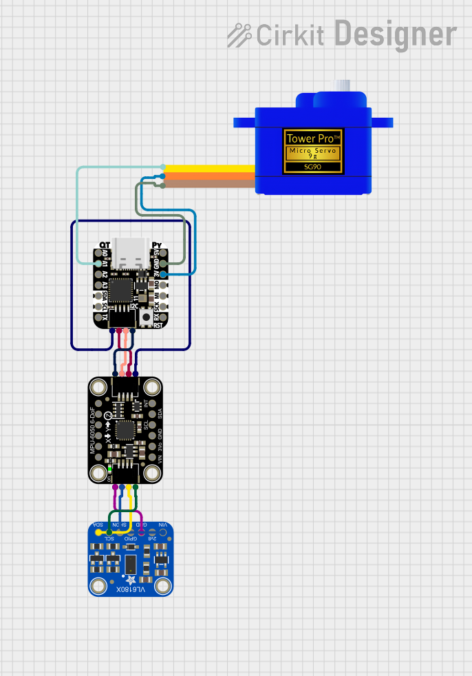 Open Project in Cirkit Designer
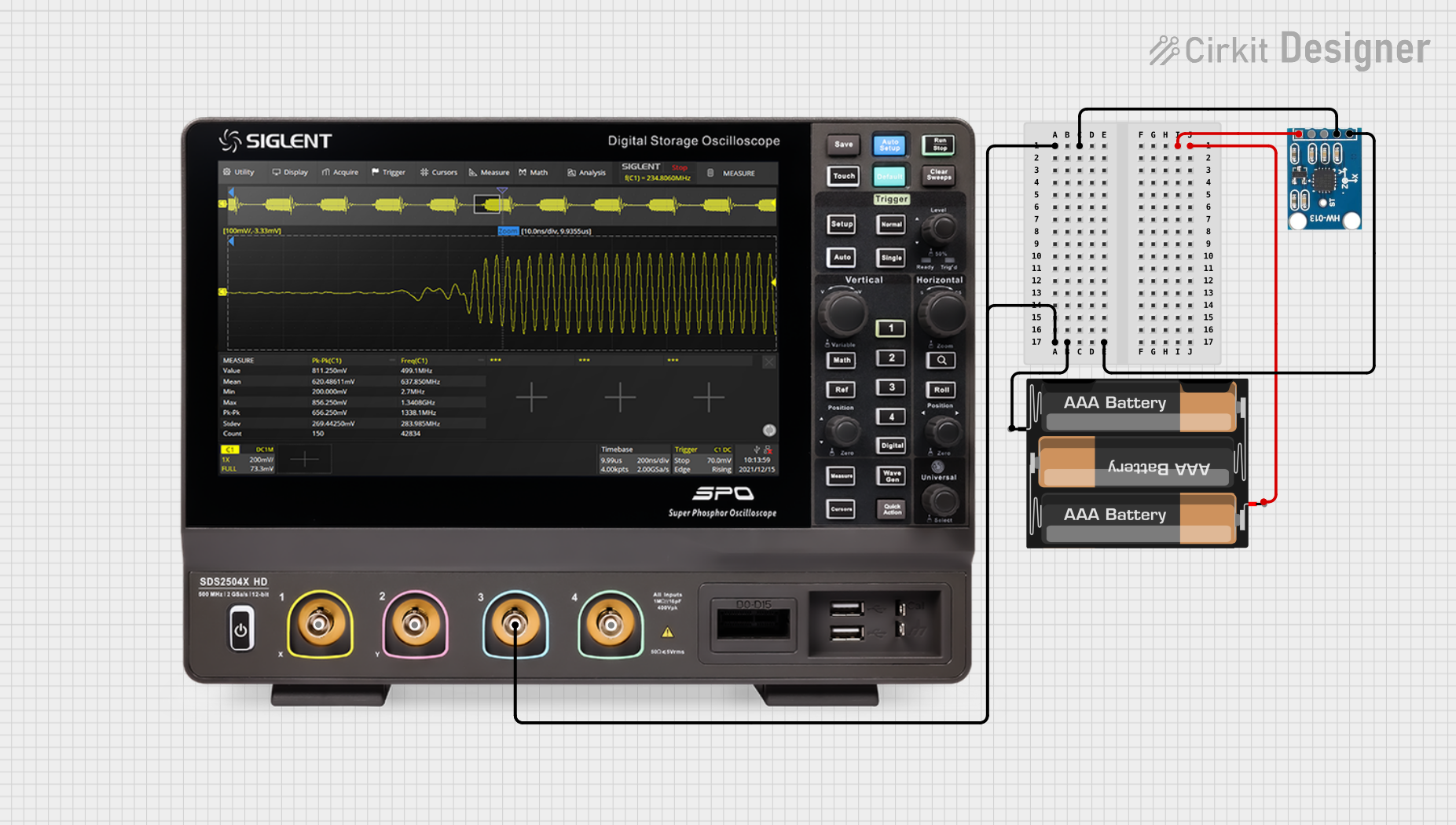 Open Project in Cirkit Designer
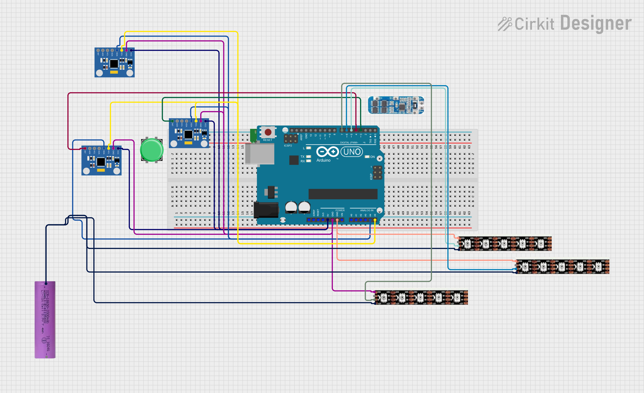 Open Project in Cirkit Designer
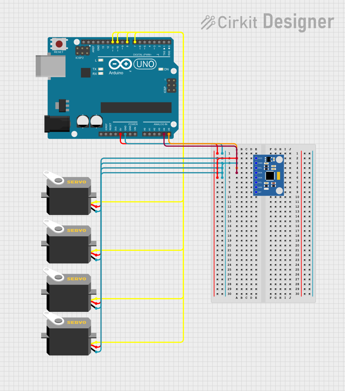 Open Project in Cirkit Designer
Explore Projects Built with SparkFun ITG-3200 Triple-Axis Gyroscope Breakout
Open Project in Cirkit DesignerOpen Project in Cirkit DesignerOpen Project in Cirkit DesignerOpen Project in Cirkit DesignerTechnical Specifications
The ITG-3200 gyroscope breakout board is built for precision and ease of use. Below are its key technical details:
Key Specifications
| Parameter | Value |
|---|---|
| Supply Voltage | 2.1V to 3.6V |
| Logic Level Compatibility | 3.3V (requires level shifting for 5V systems) |
| Measurement Range | ±2000°/s |
| Communication Interface | I2C (up to 400kHz) |
| Operating Temperature | -40°C to +85°C |
| Dimensions | 20.3mm x 20.3mm |
Pin Configuration
The ITG-3200 breakout board has 8 pins, as described in the table below:
| Pin Name | Description |
|---|---|
| VCC | Power supply input (2.1V to 3.6V). Typically connected to 3.3V. |
| GND | Ground connection. |
| SCL | I2C clock line. Connect to the SCL pin of the microcontroller. |
| SDA | I2C data line. Connect to the SDA pin of the microcontroller. |
| AD0 | I2C address selection. Connect to GND for address 0x68 or VCC for 0x69. |
| INT | Interrupt output. Can be used to signal data availability or events. |
| CLKIN | Optional external clock input (not commonly used). |
| CLKOUT | Optional clock output (not commonly used). |
Usage Instructions
Connecting the ITG-3200 to a Microcontroller
- Power Supply: Connect the VCC pin to a 3.3V power source and GND to ground.
- I2C Interface: Connect the SCL and SDA pins to the corresponding I2C pins on your microcontroller. Use pull-up resistors (typically 4.7kΩ) on the SCL and SDA lines if not already present.
- I2C Address Selection: Set the AD0 pin to GND for the default I2C address (0x68) or to VCC for the alternate address (0x69).
- Interrupt Pin (Optional): Connect the INT pin to a digital input on your microcontroller if you want to use interrupt-driven data reading.
Example Code for Arduino UNO
Below is an example Arduino sketch to read data from the ITG-3200 using the Wire library:
#include <Wire.h>

#define ITG3200_ADDR 0x68 // Default I2C address of the ITG-3200

void setup() {
  Wire.begin(); // Initialize I2C communication
  Serial.begin(9600); // Initialize serial communication for debugging

  // Configure the ITG-3200
  Wire.beginTransmission(ITG3200_ADDR);
  Wire.write(0x3E); // Power management register
  Wire.write(0x00); // Wake up the sensor
  Wire.endTransmission();

  Serial.println("ITG-3200 initialized.");
}

void loop() {
  int16_t gyroX, gyroY, gyroZ;

  // Request 6 bytes of data from the ITG-3200
  Wire.beginTransmission(ITG3200_ADDR);
  Wire.write(0x1D); // Starting register for gyro data
  Wire.endTransmission();
  Wire.requestFrom(ITG3200_ADDR, 6);

  // Read the gyro data
  if (Wire.available() == 6) {
    gyroX = (Wire.read() << 8) | Wire.read(); // Combine high and low bytes
    gyroY = (Wire.read() << 8) | Wire.read();
    gyroZ = (Wire.read() << 8) | Wire.read();
  }

  // Print the gyro data
  Serial.print("Gyro X: ");
  Serial.print(gyroX);
  Serial.print(" | Gyro Y: ");
  Serial.print(gyroY);
  Serial.print(" | Gyro Z: ");
  Serial.println(gyroZ);

  delay(100); // Delay for readability
}
Best Practices
- Use a level shifter if interfacing with a 5V microcontroller to avoid damaging the sensor.
- Place decoupling capacitors near the VCC pin to reduce noise.
- Mount the breakout board securely to minimize vibrations, which can affect readings.
- Calibrate the gyroscope before use to ensure accurate measurements.
Troubleshooting and FAQs
Common Issues
No Data or Incorrect Readings:
- Ensure the I2C connections (SCL, SDA) are correct and have pull-up resistors.
- Verify the I2C address (0x68 or 0x69) matches your configuration.
- Check the power supply voltage (2.1V to 3.6V).
Sensor Overheating:
- Ensure the sensor is not exposed to excessive heat or voltage beyond its specifications.
Unstable or Noisy Readings:
- Minimize vibrations and external interference.
- Use software filtering or averaging to smooth the data.
FAQs
Q: Can the ITG-3200 be used with a 5V microcontroller?
A: Yes, but you must use a level shifter for the I2C lines to prevent damage to the sensor.
Q: How do I calibrate the gyroscope?
A: Calibration involves reading the sensor's output while it is stationary and subtracting the offset values from subsequent readings.
Q: What is the maximum angular velocity the ITG-3200 can measure?
A: The ITG-3200 can measure angular velocities up to ±2000°/s.
Q: Can I use the ITG-3200 with SPI instead of I2C?
A: No, the ITG-3200 only supports I2C communication.
By following this documentation, you can effectively integrate the SparkFun ITG-3200 Triple-Axis Gyroscope Breakout into your projects for precise motion tracking and control.