How to Use Laser Sensor photoelectric switch: Examples, Pinouts, and Specs
Introduction
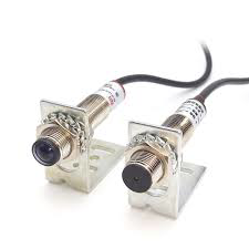
The Laser Sensor Photoelectric Switch is a device that utilizes a laser beam to detect the presence or absence of an object. This component is widely used in industrial applications for precise positioning and object detection. Its high accuracy and reliability make it an essential tool in automation, manufacturing, and quality control processes.
Explore Projects Built with Laser Sensor photoelectric switch
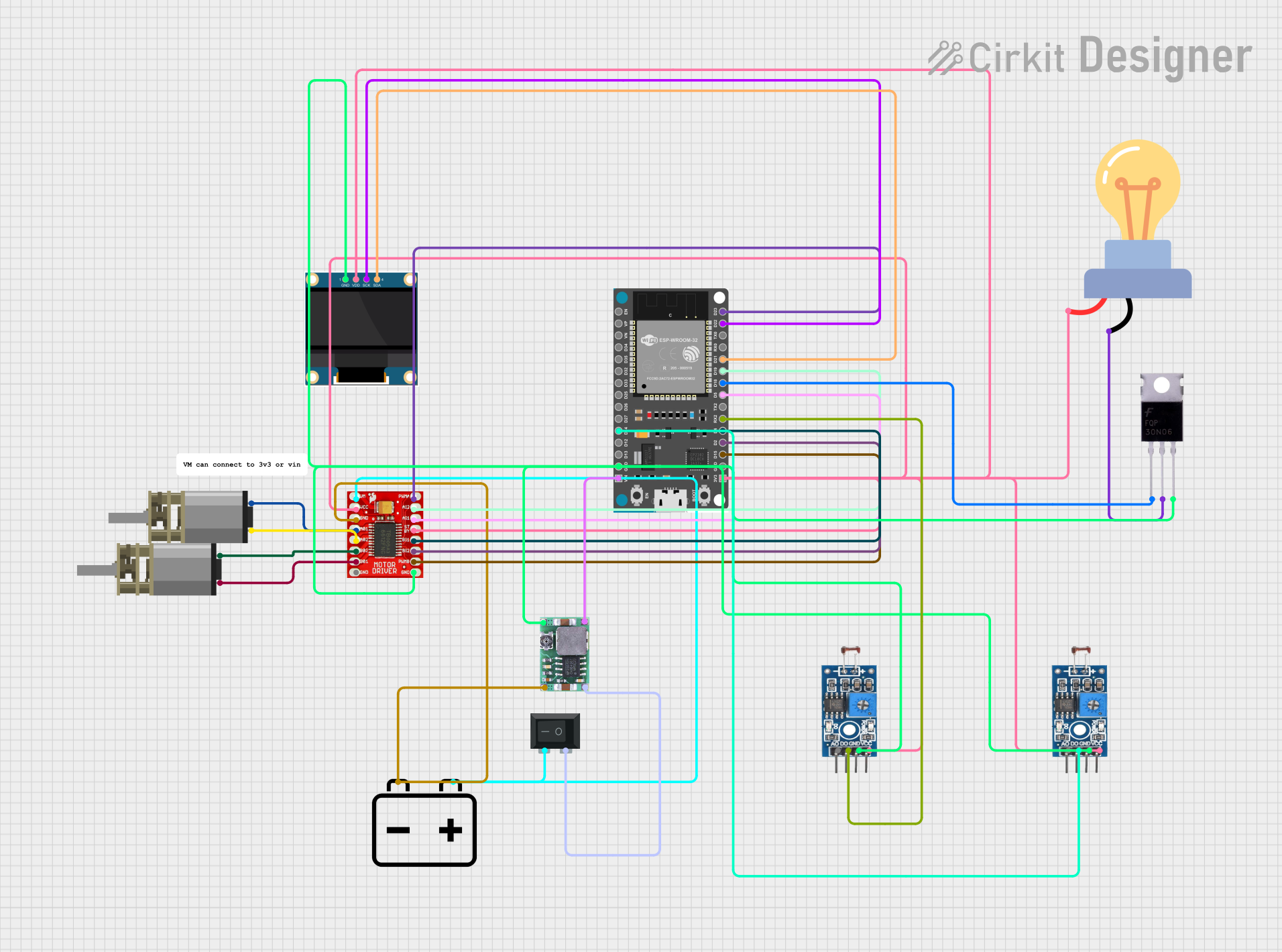
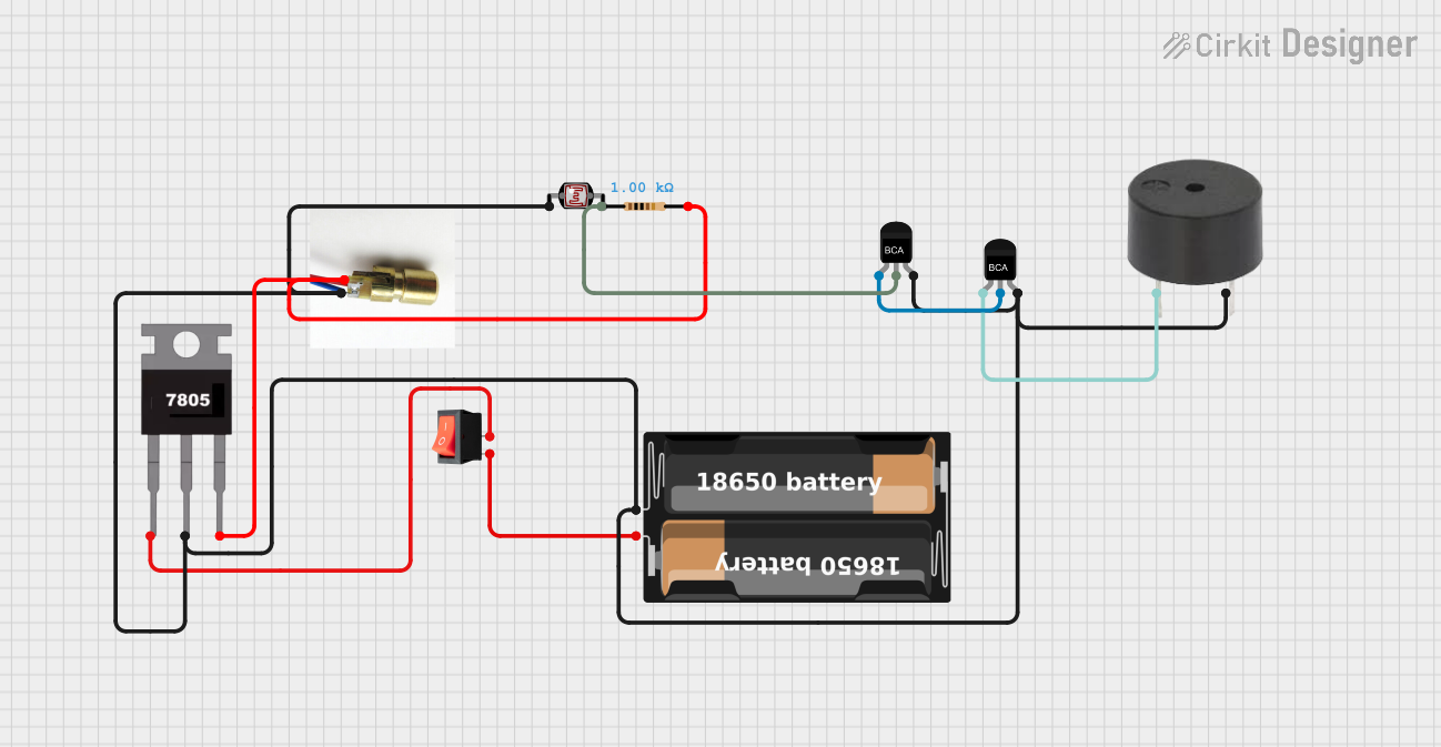

Explore Projects Built with Laser Sensor photoelectric switch
Technical Specifications
Key Technical Details
| Parameter | Value |
|---|---|
| Operating Voltage | 5V - 24V DC |
| Current Consumption | ≤ 30mA |
| Detection Range | 0.1m - 10m |
| Response Time | ≤ 1ms |
| Output Type | NPN/PNP, NO/NC |
| Laser Wavelength | 650nm (Red) |
| Operating Temperature | -10°C to 50°C |
| Housing Material | ABS Plastic |
Pin Configuration and Descriptions
| Pin Number | Pin Name | Description |
|---|---|---|
| 1 | VCC | Power Supply (5V - 24V DC) |
| 2 | GND | Ground |
| 3 | OUT | Output Signal (NPN/PNP, NO/NC) |
Usage Instructions
How to Use the Component in a Circuit
- Power Supply Connection: Connect the VCC pin to a 5V - 24V DC power supply and the GND pin to the ground of the power supply.
- Output Signal Connection: Connect the OUT pin to the input pin of a microcontroller or any other control circuit to read the output signal.
Important Considerations and Best Practices
- Alignment: Ensure that the laser beam is properly aligned with the target object for accurate detection.
- Environment: Avoid using the sensor in environments with excessive dust, smoke, or reflective surfaces, as these can interfere with the laser beam.
- Mounting: Securely mount the sensor to prevent any movement or vibration that could affect its accuracy.
- Power Supply: Use a stable and regulated power supply to ensure consistent performance.
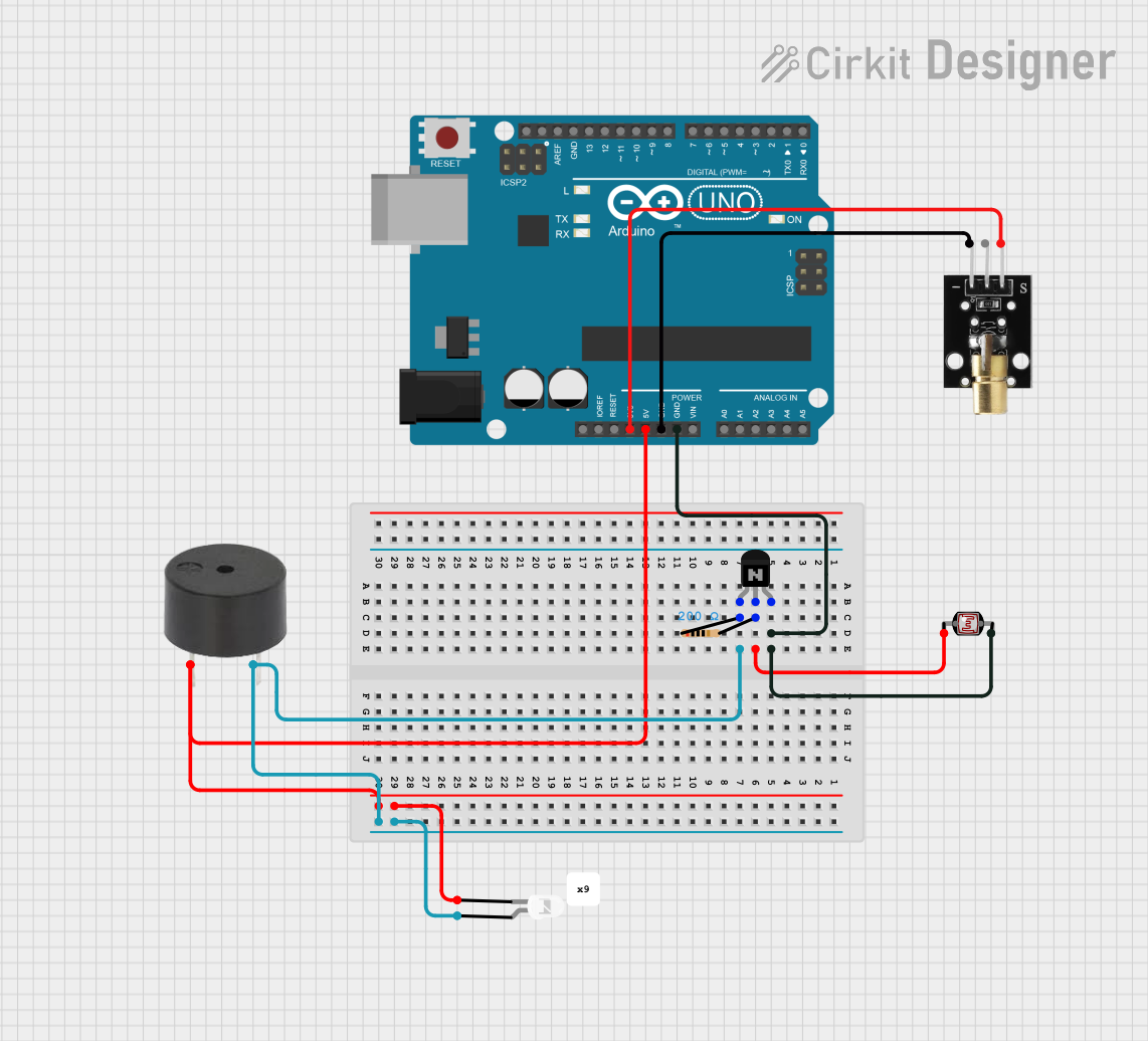
Example: Connecting to an Arduino UNO
Circuit Diagram
Laser Sensor Photoelectric Switch
    VCC  -> 5V (Arduino UNO)
    GND  -> GND (Arduino UNO)
    OUT  -> Digital Pin 2 (Arduino UNO)
Arduino Code
// Define the pin connected to the laser sensor output
const int sensorPin = 2;

// Variable to store the sensor state
int sensorState = 0;

void setup() {
  // Initialize the serial communication
  Serial.begin(9600);

  // Set the sensor pin as input
  pinMode(sensorPin, INPUT);
}

void loop() {
  // Read the state of the sensor
  sensorState = digitalRead(sensorPin);

  // Print the sensor state to the serial monitor
  if (sensorState == HIGH) {
    Serial.println("Object Detected");
  } else {
    Serial.println("No Object Detected");
  }

  // Small delay to avoid flooding the serial monitor
  delay(500);
}
Troubleshooting and FAQs
Common Issues Users Might Face
No Detection: The sensor does not detect any object.
- Solution: Check the alignment of the laser beam and ensure it is properly aimed at the target object. Verify the power supply voltage and connections.
False Triggers: The sensor gives false detection signals.
- Solution: Ensure the sensor is not exposed to reflective surfaces or excessive dust. Adjust the sensitivity settings if available.
Intermittent Detection: The sensor detects objects intermittently.
- Solution: Securely mount the sensor to prevent movement or vibration. Check for any loose connections in the circuit.
FAQs
Q1: Can the sensor detect transparent objects?
- A1: The sensor may have difficulty detecting transparent objects due to the laser beam passing through them. Consider using a sensor specifically designed for transparent object detection.
Q2: What is the maximum detection range of the sensor?
- A2: The maximum detection range of the sensor is 10 meters.
Q3: Can the sensor be used outdoors?
- A3: The sensor is designed for indoor use. Using it outdoors may expose it to environmental factors that can affect its performance.
Q4: How do I choose between NPN and PNP output types?
- A4: The choice between NPN and PNP output types depends on the input requirements of your control circuit or microcontroller. NPN outputs are typically used with sinking inputs, while PNP outputs are used with sourcing inputs.
By following this documentation, users can effectively integrate and utilize the Laser Sensor Photoelectric Switch in their projects, ensuring accurate and reliable object detection.