Cirkit Designer Logo
Cirkit Designer
Your all-in-one circuit design IDE
Home / 
Component Documentation

How to Use I/O 8 pin expander (I2C): Examples, Pinouts, and Specs

Image of I/O 8 pin expander (I2C)
Cirkit Designer LogoDesign with I/O 8 pin expander (I2C) in Cirkit Designer

Introduction

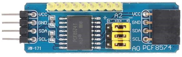
The HW-171 I2C 8 Pin Expander is an electronic component designed to increase the number of input/output (I/O) pins available on a microcontroller or microprocessor. It communicates via the I2C protocol, a two-wire serial communication interface, allowing multiple devices to be connected to a single bus. This expander is particularly useful in projects where the number of available I/O pins on the main controller is limited. Common applications include:

  • Expanding the I/O capability of microcontrollers like Arduino, Raspberry Pi, etc.
  • Robotics, where multiple sensors or actuators are required.
  • Home automation systems for controlling lights, thermostats, and other peripherals.
  • Embedded systems requiring additional I/O ports without redesigning the main board.

Explore Projects Built with I/O 8 pin expander (I2C)

Use Cirkit Designer to design, explore, and prototype these projects online. Some projects support real-time simulation. Click "Open Project" to start designing instantly!
ESP32-Based I2C Communication Hub with Multiplexer and Expander
Image of Lights: A project utilizing I/O 8 pin expander (I2C) in a practical application
This circuit features an Olimex ESP32-EVB microcontroller unit (MCU) for processing and connectivity, interfaced with an MCP23017 I/O expander and an Adafruit TCA9548A I2C multiplexer to expand the number of I/O lines and allow multiple I2C devices to communicate with the MCU over the same bus. Pull-up resistors are connected to the I2C lines for proper bus operation, and both the MCP23017 and TCA9548A have their reset lines pulled high, likely for normal operation without external reset control.
Cirkit Designer LogoOpen Project in Cirkit Designer
I2C-Controlled Relay Switching with ESP32 and MCP23017 for Home Automation
Image of Vloerverwarming: A project utilizing I/O 8 pin expander (I2C) in a practical application
This circuit appears to be a control system utilizing two MCP23017 I/O expanders interfaced with an Olimex ESP32-EVB microcontroller via I2C communication, as indicated by the SDA and SCL connections with pull-up resistors. The MCP23017 expanders control an 8-channel relay module, allowing the microcontroller to switch various loads, potentially for home automation or industrial control. Additionally, there is an Adafruit ADS1115 16-bit ADC for analog signal measurement, and several heating actuators and a thermostat are connected, suggesting temperature control functionality.
Cirkit Designer LogoOpen Project in Cirkit Designer
ESP32-Based OLED Display Interface
Image of d: A project utilizing I/O 8 pin expander (I2C) in a practical application
This circuit features an ESP32 microcontroller connected to an OLED 1.3" display. The ESP32's GPIO pins 21 and 22 are used for I2C communication (SDA and SCL respectively) with the OLED display. The display is powered by the 5V output from the ESP32, and both devices share a common ground.
Cirkit Designer LogoOpen Project in Cirkit Designer
MCP23017-Expanded I/O Interface with ADS1115 ADC and ESP32 Control
Image of door and window sensors: A project utilizing I/O 8 pin expander (I2C) in a practical application
This circuit features two MCP23017 I/O expanders interfaced with multiple switches, allowing for the expansion of input capabilities. The MCP23017s are connected via I2C to an Olimex ESP32-EVB microcontroller, which likely manages the input states from the switches. Additionally, an Adafruit ADS1115 16-bit ADC is included, suggesting that some analog inputs are being monitored, with the ADC also interfaced with the ESP32 via I2C.
Cirkit Designer LogoOpen Project in Cirkit Designer

Explore Projects Built with I/O 8 pin expander (I2C)

Use Cirkit Designer to design, explore, and prototype these projects online. Some projects support real-time simulation. Click "Open Project" to start designing instantly!
Image of Lights: A project utilizing I/O 8 pin expander (I2C) in a practical application
ESP32-Based I2C Communication Hub with Multiplexer and Expander
This circuit features an Olimex ESP32-EVB microcontroller unit (MCU) for processing and connectivity, interfaced with an MCP23017 I/O expander and an Adafruit TCA9548A I2C multiplexer to expand the number of I/O lines and allow multiple I2C devices to communicate with the MCU over the same bus. Pull-up resistors are connected to the I2C lines for proper bus operation, and both the MCP23017 and TCA9548A have their reset lines pulled high, likely for normal operation without external reset control.
Cirkit Designer LogoOpen Project in Cirkit Designer
Image of Vloerverwarming: A project utilizing I/O 8 pin expander (I2C) in a practical application
I2C-Controlled Relay Switching with ESP32 and MCP23017 for Home Automation
This circuit appears to be a control system utilizing two MCP23017 I/O expanders interfaced with an Olimex ESP32-EVB microcontroller via I2C communication, as indicated by the SDA and SCL connections with pull-up resistors. The MCP23017 expanders control an 8-channel relay module, allowing the microcontroller to switch various loads, potentially for home automation or industrial control. Additionally, there is an Adafruit ADS1115 16-bit ADC for analog signal measurement, and several heating actuators and a thermostat are connected, suggesting temperature control functionality.
Cirkit Designer LogoOpen Project in Cirkit Designer
Image of d: A project utilizing I/O 8 pin expander (I2C) in a practical application
ESP32-Based OLED Display Interface
This circuit features an ESP32 microcontroller connected to an OLED 1.3" display. The ESP32's GPIO pins 21 and 22 are used for I2C communication (SDA and SCL respectively) with the OLED display. The display is powered by the 5V output from the ESP32, and both devices share a common ground.
Cirkit Designer LogoOpen Project in Cirkit Designer
Image of door and window sensors: A project utilizing I/O 8 pin expander (I2C) in a practical application
MCP23017-Expanded I/O Interface with ADS1115 ADC and ESP32 Control
This circuit features two MCP23017 I/O expanders interfaced with multiple switches, allowing for the expansion of input capabilities. The MCP23017s are connected via I2C to an Olimex ESP32-EVB microcontroller, which likely manages the input states from the switches. Additionally, an Adafruit ADS1115 16-bit ADC is included, suggesting that some analog inputs are being monitored, with the ADC also interfaced with the ESP32 via I2C.
Cirkit Designer LogoOpen Project in Cirkit Designer

Technical Specifications

Key Technical Details

  • Operating Voltage: 2.3V to 5.5V
  • I2C Bus Voltage: Same as operating voltage
  • Number of I/O Expander Pins: 8
  • Maximum Output Current per Pin: 25 mA
  • I2C Address Range: Configurable
  • Operating Temperature Range: -40°C to +85°C

Pin Configuration and Descriptions

Pin Number Pin Name Description
1 VDD Power supply (2.3V to 5.5V)
2 GND Ground connection
3 SCL Serial Clock Line for I2C communication
4 SDA Serial Data Line for I2C communication
5-12 IO0-IO7 I/O Expander Pins

Usage Instructions

Connecting to a Circuit

  1. Connect the VDD pin to the power supply (matching the operating voltage of your microcontroller).
  2. Connect the GND pin to the ground of your power supply.
  3. Connect the SCL and SDA pins to the corresponding I2C pins on your microcontroller.
  4. The IO0-IO7 pins are now ready to be used as additional I/O pins.

Important Considerations and Best Practices

  • Ensure pull-up resistors are connected to the SCL and SDA lines if they are not already present on the microcontroller board.
  • Avoid exceeding the maximum current rating per I/O pin to prevent damage to the expander.
  • Use proper decoupling capacitors close to the VDD pin to minimize power supply noise.
  • When using long I2C bus lines, consider using bus extenders or active I2C bus buffers to maintain signal integrity.

Example Code for Arduino UNO

#include <Wire.h>

// Define the I2C address for the expander (check the datasheet for address configuration)
const int expanderAddress = 0x20;

void setup() {
  Wire.begin(); // Initialize I2C communication
  Serial.begin(9600); // Start serial communication for debugging
  // Configure all pins on the expander as outputs (replace with actual configuration method)
  // This is a placeholder as the actual configuration will depend on the expander's internal registers
}

void loop() {
  // Example: Turn on all the expander pins
  Wire.beginTransmission(expanderAddress);
  Wire.write(0xFF); // Sending a byte with all bits set to 1 (again, replace with actual command)
  Wire.endTransmission();
  delay(1000);

  // Example: Turn off all the expander pins
  Wire.beginTransmission(expanderAddress);
  Wire.write(0x00); // Sending a byte with all bits set to 0
  Wire.endTransmission();
  delay(1000);
}

Troubleshooting and FAQs

Common Issues

  • I2C Communication Failure: Check connections, ensure pull-up resistors are in place, and verify that no other device on the bus has a conflicting address.
  • Insufficient Power Supply: Ensure that the power supply can deliver sufficient current for all connected devices.
  • Intermittent Functionality: Check for loose connections and consider using shorter cables or active I2C bus buffers.

FAQs

Q: Can I connect multiple I2C expanders to the same bus? A: Yes, as long as each expander has a unique I2C address.

Q: How do I change the I2C address of the expander? A: The I2C address is typically set by configuring hardware address pins or internal registers. Refer to the specific datasheet of the HW-171 for details.

Q: What is the maximum length for the I2C bus cables? A: The maximum length depends on the bus speed, cable capacitance, and pull-up resistors. For standard 100kHz I2C, lengths up to 1 meter are usually safe. For longer distances, consider using I2C bus extenders.

Q: Can the expander pins source and sink current? A: Yes, but ensure that the current does not exceed the maximum rating per pin.

This documentation provides an overview of the HW-171 I2C 8 Pin Expander. For more detailed information, please refer to the manufacturer's datasheet and application notes.