How to Use ESP32-C6 Zero: Examples, Pinouts, and Specs
Introduction
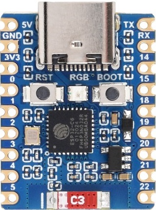
The ESP32-C6 Zero is a highly integrated Wi-Fi and Bluetooth® microcontroller SoC (System on Chip) that is part of the ESP32 series known for its low-power consumption and robust feature set. It is equipped with an Xtensa® single-core 32-bit LX7 CPU, making it a powerful choice for smart IoT devices. The ESP32-C6 Zero is designed to provide secure and reliable connectivity with advanced security features, making it suitable for a wide range of applications such as smart home devices, industrial automation, health monitoring, and more.
Explore Projects Built with ESP32-C6 Zero

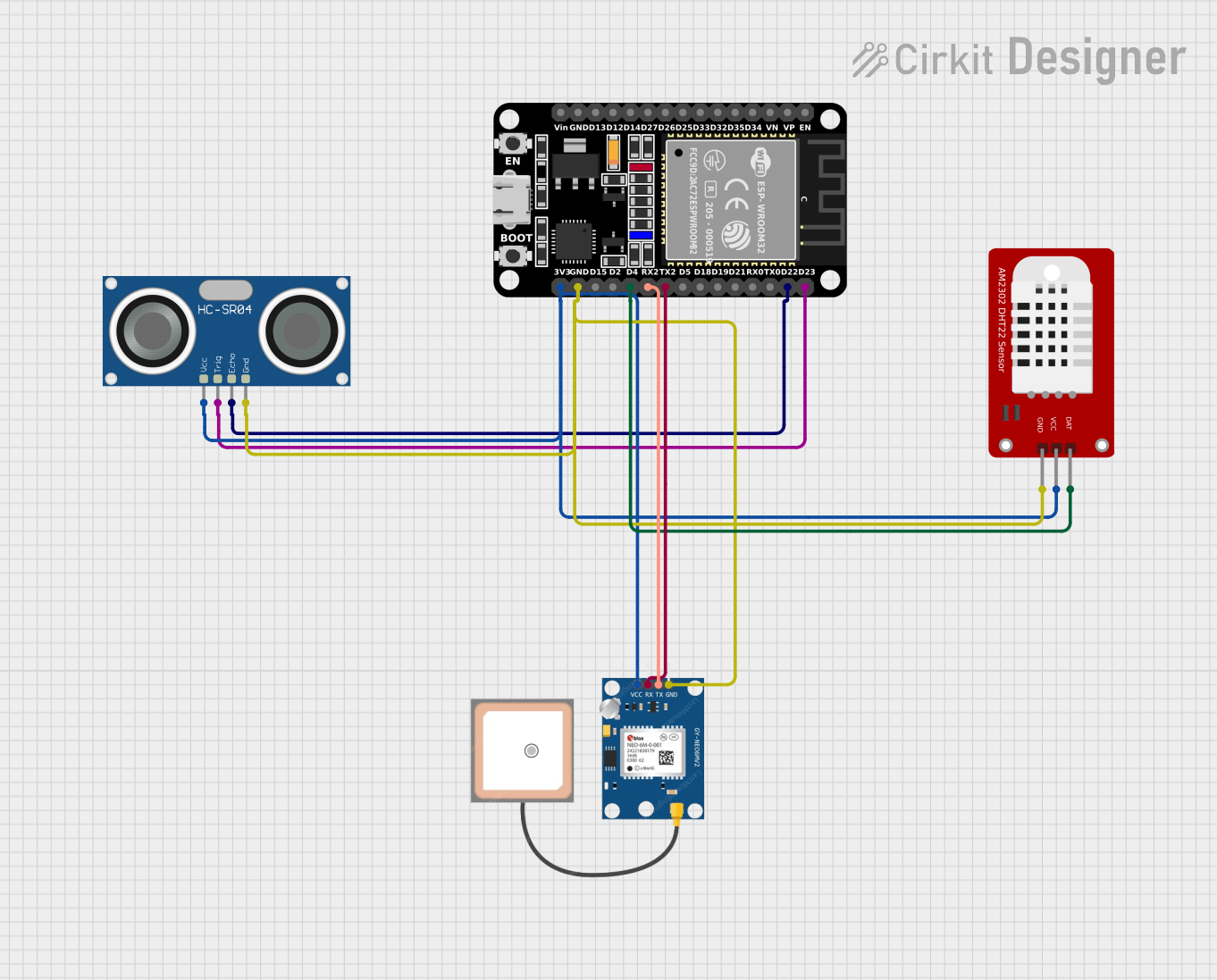
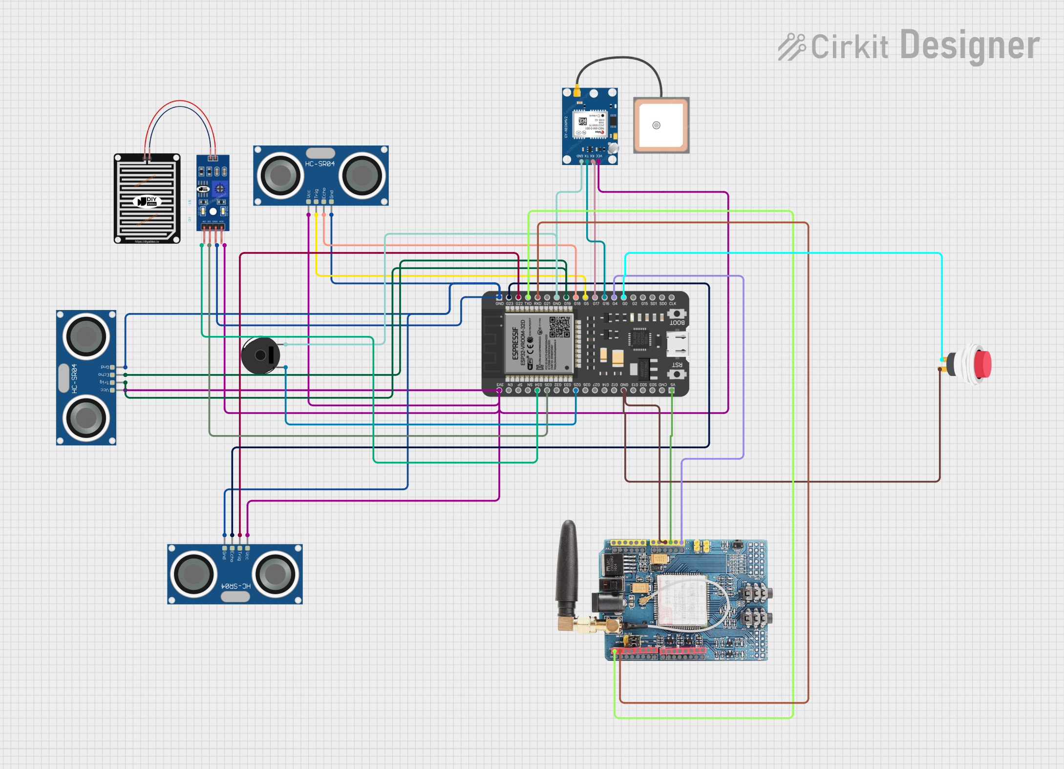

Explore Projects Built with ESP32-C6 Zero
Technical Specifications
Key Technical Details
- CPU: Xtensa® single-core 32-bit LX7
- Operating Voltage: 3.0V to 3.6V
- I/O Voltage: 3.3V
- Wi-Fi: IEEE 802.11b/g/n (2.4 GHz)
- Bluetooth®: Bluetooth® 5 (LE)
- RAM: 520 KB SRAM
- Flash Memory: Up to 16 MB of external QSPI flash
- GPIO: Multiple GPIO pins with various functions
- ADC: 12-bit SAR ADC
- DAC: Two 8-bit DACs
- Security: Secure boot, Flash encryption, 1024-bit OTP, hardware accelerated cryptographic functions (AES, SHA-2, RSA, ECC, random number generator)
Pin Configuration and Descriptions
| Pin Number | Name | Function |
|---|---|---|
| 1 | 3V3 | Power supply (3.3V) |
| 2 | GND | Ground |
| 3 | EN | Chip enable (active high) |
| 4 | IO0 | General-purpose I/O and programming pin |
| ... | ... | ... |
| n | IOx | General-purpose I/O pin x |
Note: This is a simplified representation. The actual ESP32-C6 Zero has more pins, each with specific functions.
Usage Instructions
Integrating ESP32-C6 Zero into a Circuit
Power Supply: Ensure that the power supply is within the operating voltage range (3.0V to 3.6V). A 3.3V voltage regulator can be used if necessary.
Programming: Connect IO0 to GND to enter programming mode. Use a USB-to-Serial converter to upload firmware.
Wi-Fi and Bluetooth®: Utilize the provided libraries to enable and configure Wi-Fi and Bluetooth® functionalities.
GPIO Pins: Configure the GPIO pins according to the requirements of your project. Take note of the maximum current that each pin can handle.
Antenna: For optimal wireless performance, connect an appropriate antenna to the U.FL connector or use the PCB antenna, if available.
Best Practices
- Use a decoupling capacitor close to the power supply pins to filter out noise.
- Avoid long wires for the antenna connection to minimize signal loss.
- Follow the recommended PCB layout guidelines provided by the manufacturer for RF performance and EMC compliance.
- Implement proper ESD protection, especially for GPIO pins that will be exposed to external connections.
Troubleshooting and FAQs
Common Issues
- Device Not Booting: Ensure that the power supply is stable and within the specified range. Check the EN pin is pulled high.
- Wi-Fi/Bluetooth® Not Functioning: Verify that the antenna is properly connected and that the wireless functionality is correctly initialized in the code.
- I/O Pin Malfunction: Check for shorts or incorrect pin configurations in the code. Ensure that the pins are not being overloaded.
Solutions and Tips
- Power Issues: Use a multimeter to verify the voltage levels at the power supply pins.
- Connectivity Issues: Use example code to test basic Wi-Fi and Bluetooth® functionalities before implementing custom logic.
- Code Debugging: Use serial output to debug and track the program flow.
FAQs
Q: Can the ESP32-C6 Zero run on battery power?
- A: Yes, it is designed for low-power applications and can be powered by batteries. Consider power management strategies for longer battery life.
Q: What development environments are compatible with the ESP32-C6 Zero?
- A: The ESP32-C6 Zero can be programmed using the ESP-IDF, Arduino IDE, and other compatible development platforms.
Q: How do I update the firmware on the ESP32-C6 Zero?
- A: Firmware can be updated using the USB-to-Serial converter and the appropriate flashing tools provided by the manufacturer.
Example Code for Arduino UNO
#include <WiFi.h>

// Replace with your network credentials
const char* ssid = "your_SSID";
const char* password = "your_PASSWORD";

void setup() {
  Serial.begin(115200);

  // Connect to Wi-Fi
  WiFi.begin(ssid, password);
  while (WiFi.status() != WL_CONNECTED) {
    delay(500);
    Serial.println("Connecting to WiFi...");
  }

  Serial.println("Connected to WiFi");
}

void loop() {
  // Put your main code here, to run repeatedly:
}
Note: This example assumes the use of the Arduino IDE with the ESP32-C6 Zero board support installed.
Remember to follow the 80-character line length limit for code comments, wrapping text as needed. This ensures readability and maintainability of the code.