How to Use 8-pin RELAY: Examples, Pinouts, and Specs
Introduction
The 8-Pin RELAY (Manufacturer: Electrix, Part ID: 8-Pin RELAY) is an electromechanical switch designed to control high-power circuits using low-power signals. It operates by energizing an electromagnetic coil, which mechanically opens or closes its internal contacts. This component is widely used in applications requiring electrical isolation between control and load circuits.
Explore Projects Built with 8-pin RELAY


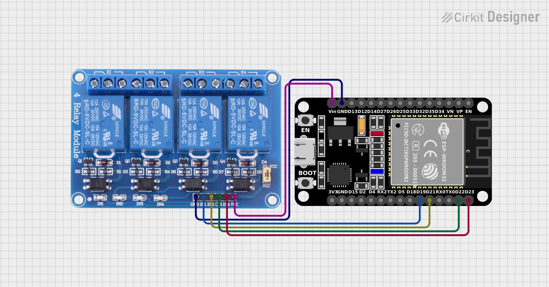
Explore Projects Built with 8-pin RELAY
Common Applications and Use Cases
- Home Automation: Controlling appliances like lights, fans, and motors.
- Industrial Control Systems: Switching high-power devices such as pumps and heaters.
- Automotive Systems: Managing headlights, horns, and other electrical components.
- Microcontroller Projects: Interfacing with Arduino, Raspberry Pi, or other microcontrollers to control external devices.
Technical Specifications
The following table outlines the key technical details of the 8-Pin RELAY:
| Parameter | Value |
|---|---|
| Manufacturer | Electrix |
| Part ID | 8-Pin RELAY |
| Coil Voltage | 5V DC, 12V DC, or 24V DC (varies) |
| Coil Resistance | 70 Ω (5V), 290 Ω (12V), 960 Ω (24V) |
| Contact Configuration | SPDT (Single Pole Double Throw) |
| Contact Rating | 10A at 250V AC / 10A at 30V DC |
| Dielectric Strength | 1500V AC (coil to contacts) |
| Operating Temperature | -40°C to +85°C |
| Dimensions | 28mm x 12mm x 15mm |
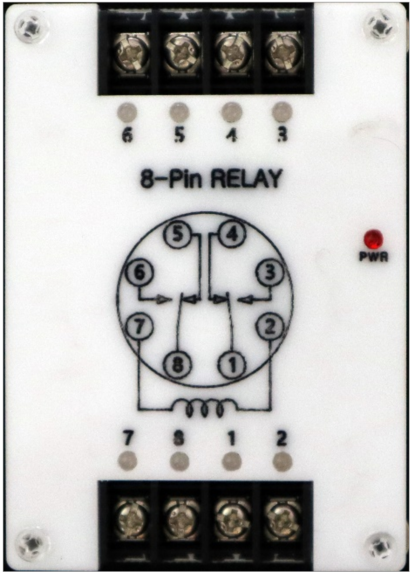
Pin Configuration and Descriptions
The 8-Pin RELAY has the following pinout:
| Pin Number | Name | Description |
|---|---|---|
| 1 | Coil+ | Positive terminal of the relay coil |
| 2 | Coil- | Negative terminal of the relay coil |
| 3 | Common (COM) | Common terminal for the relay contacts |
| 4 | Normally Open (NO) | Contact that is open when the relay is de-energized |
| 5 | Normally Closed (NC) | Contact that is closed when the relay is de-energized |
| 6, 7, 8 | Not Connected | Reserved or unused pins |
Usage Instructions
How to Use the 8-Pin RELAY in a Circuit
- Power the Coil: Connect the coil terminals (Pin 1 and Pin 2) to a DC voltage source matching the relay's rated coil voltage (e.g., 5V, 12V, or 24V).
- Control the Load:
- Connect the load to the Common (COM) terminal (Pin 3).
- Use the Normally Open (NO) terminal (Pin 4) if you want the load to be powered only when the relay is energized.
- Use the Normally Closed (NC) terminal (Pin 5) if you want the load to be powered when the relay is not energized.
- Isolation: Ensure proper electrical isolation between the control circuit (coil) and the load circuit (contacts).
Important Considerations and Best Practices
- Diode Protection: Place a flyback diode (e.g., 1N4007) across the coil terminals to protect the driving circuit from voltage spikes when the relay is de-energized.
- Current Rating: Ensure the load current does not exceed the relay's contact rating (10A).
- Power Supply: Use a stable DC power supply to drive the relay coil.
- Mounting: Secure the relay in a socket or PCB to prevent mechanical stress.
Example: Using the 8-Pin RELAY with Arduino UNO
Below is an example of how to control the 8-Pin RELAY using an Arduino UNO:
// Example: Controlling an 8-Pin RELAY with Arduino UNO
// Pin 7 of Arduino is used to control the relay

#define RELAY_PIN 7  // Define the Arduino pin connected to the relay's coil

void setup() {
  pinMode(RELAY_PIN, OUTPUT);  // Set the relay pin as an output
  digitalWrite(RELAY_PIN, LOW); // Ensure the relay is off initially
}

void loop() {
  digitalWrite(RELAY_PIN, HIGH); // Turn the relay on (energize the coil)
  delay(1000);                   // Wait for 1 second
  digitalWrite(RELAY_PIN, LOW);  // Turn the relay off (de-energize the coil)
  delay(1000);                   // Wait for 1 second
}
Note: Connect a transistor (e.g., 2N2222) and a flyback diode to drive the relay safely from the Arduino, as the Arduino pin cannot directly supply enough current for the relay coil.
Troubleshooting and FAQs
Common Issues and Solutions
Relay Not Switching:
- Cause: Insufficient coil voltage or current.
- Solution: Verify the power supply voltage and current match the relay's specifications.
Load Not Powered:
- Cause: Incorrect wiring of the load to the relay contacts.
- Solution: Double-check the connections to the COM, NO, and NC terminals.
Arduino Resetting When Relay Activates:
- Cause: Voltage spikes from the relay coil affecting the Arduino.
- Solution: Add a flyback diode across the coil terminals and use a separate power supply for the relay.
Relay Buzzing or Chattering:
- Cause: Unstable power supply or insufficient drive current.
- Solution: Use a stable power source and ensure the driving circuit can supply adequate current.
FAQs
Q: Can I use the 8-Pin RELAY with AC loads?
A: Yes, the relay can handle AC loads up to 250V, provided the current does not exceed 10A.Q: What is the purpose of the flyback diode?
A: The flyback diode protects the driving circuit from voltage spikes generated when the relay coil is de-energized.Q: Can I use the relay without a microcontroller?
A: Yes, you can control the relay using a simple switch or any other low-power control signal.
This concludes the documentation for the Electrix 8-Pin RELAY.