How to Use LSM6DS3: Examples, Pinouts, and Specs
Introduction
The LSM6DS3 is a high-performance 6-axis inertial measurement unit (IMU) manufactured by STMicroelectronics. It integrates a 3-axis accelerometer and a 3-axis gyroscope into a single compact package, enabling precise motion sensing and orientation tracking. The LSM6DS3 is widely used in applications such as smartphones, wearables, gaming devices, drones, and other IoT devices requiring motion detection and gesture recognition.
This component is designed for low power consumption and high accuracy, making it suitable for battery-powered devices. It supports advanced features like step detection, tilt detection, and activity recognition, which are implemented through its embedded finite state machine and machine learning core.
Explore Projects Built with LSM6DS3

Explore Projects Built with LSM6DS3
Technical Specifications
Key Technical Details
| Parameter | Value |
|---|---|
| Manufacturer | STMicroelectronics |
| Part Number | LSM6DSV32X |
| Sensor Type | 6-axis IMU (3-axis accelerometer + 3-axis gyroscope) |
| Operating Voltage | 1.71V to 3.6V |
| Accelerometer Range | ±2g, ±4g, ±8g, ±16g |
| Gyroscope Range | ±125, ±250, ±500, ±1000, ±2000 dps |
| Output Data Rate (ODR) | Up to 6.66 kHz |
| Interface | I²C, SPI |
| Power Consumption | 0.65 mA (accelerometer + gyroscope in high-performance mode) |
| Operating Temperature | -40°C to +85°C |
| Package | LGA-14 (2.5 mm x 3.0 mm x 0.83 mm) |
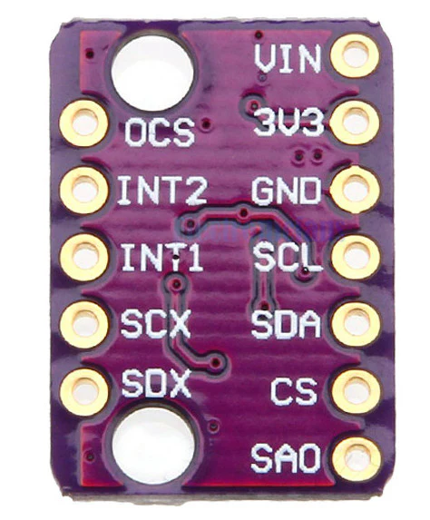
Pin Configuration and Descriptions
The LSM6DS3 comes in a 14-pin LGA package. Below is the pin configuration:
| Pin Number | Pin Name | Description |
|---|---|---|
| 1 | VDD | Power supply (1.71V to 3.6V) |
| 2 | VDDIO | I/O interface voltage supply |
| 3 | GND | Ground |
| 4 | SCL/SPC | I²C serial clock / SPI serial port clock |
| 5 | SDA/SDI/SDO | I²C serial data / SPI data in / SPI data out |
| 6 | CS | SPI chip select (active low) |
| 7 | INT1 | Interrupt 1 output |
| 8 | INT2 | Interrupt 2 output |
| 9-14 | NC | Not connected (leave floating) |
Usage Instructions
How to Use the LSM6DS3 in a Circuit
- Power Supply: Connect the VDD pin to a 1.8V or 3.3V power source, and the VDDIO pin to the desired I/O voltage level. Connect the GND pin to the ground of the circuit.
- Communication Interface: Choose between I²C or SPI for communication:
- For I²C, connect the SCL and SDA pins to the corresponding I²C lines on your microcontroller. Use pull-up resistors (typically 4.7 kΩ) on both lines.
- For SPI, connect the SCL/SPC, SDA/SDI/SDO, and CS pins to the corresponding SPI lines on your microcontroller.
- Interrupts: Use the INT1 and INT2 pins to receive interrupt signals for events like data ready, step detection, or activity recognition.
- Bypass Unused Pins: Leave the NC pins floating as they are not connected internally.
Important Considerations and Best Practices
- Voltage Levels: Ensure that the VDD and VDDIO voltages are within the specified range to avoid damage to the component.
- Decoupling Capacitors: Place a 0.1 µF ceramic capacitor close to the VDD pin to filter out noise.
- Mounting: The LSM6DS3 is sensitive to mechanical stress. Mount it carefully to avoid introducing errors in motion sensing.
- Calibration: Perform sensor calibration to improve accuracy, especially for applications requiring precise measurements.
Example Code for Arduino UNO
Below is an example of how to interface the LSM6DS3 with an Arduino UNO using the I²C interface:
#include <Wire.h>

// LSM6DS3 I2C address
#define LSM6DS3_ADDR 0x6A

// Register addresses
#define WHO_AM_I 0x0F
#define CTRL1_XL 0x10
#define CTRL2_G  0x11
#define OUTX_L_XL 0x28

void setup() {
  Wire.begin(); // Initialize I2C communication
  Serial.begin(9600); // Initialize serial communication

  // Check if the LSM6DS3 is connected
  Wire.beginTransmission(LSM6DS3_ADDR);
  Wire.write(WHO_AM_I);
  Wire.endTransmission();
  Wire.requestFrom(LSM6DS3_ADDR, 1);
  if (Wire.available()) {
    byte whoAmI = Wire.read();
    if (whoAmI == 0x69) { // Expected WHO_AM_I response
      Serial.println("LSM6DS3 detected!");
    } else {
      Serial.println("Device not recognized.");
    }
  }

  // Configure accelerometer (±2g, 104 Hz ODR)
  Wire.beginTransmission(LSM6DS3_ADDR);
  Wire.write(CTRL1_XL);
  Wire.write(0x40); // 104 Hz, ±2g
  Wire.endTransmission();

  // Configure gyroscope (±250 dps, 104 Hz ODR)
  Wire.beginTransmission(LSM6DS3_ADDR);
  Wire.write(CTRL2_G);
  Wire.write(0x40); // 104 Hz, ±250 dps
  Wire.endTransmission();
}

void loop() {
  // Read accelerometer data
  Wire.beginTransmission(LSM6DS3_ADDR);
  Wire.write(OUTX_L_XL);
  Wire.endTransmission();
  Wire.requestFrom(LSM6DS3_ADDR, 6); // Read 6 bytes (X, Y, Z)

  if (Wire.available() == 6) {
    int16_t accelX = Wire.read() | (Wire.read() << 8);
    int16_t accelY = Wire.read() | (Wire.read() << 8);
    int16_t accelZ = Wire.read() | (Wire.read() << 8);

    Serial.print("Accel X: "); Serial.print(accelX);
    Serial.print(" Y: "); Serial.print(accelY);
    Serial.print(" Z: "); Serial.println(accelZ);
  }

  delay(100); // Delay for readability
}
Troubleshooting and FAQs
Common Issues
- Device Not Detected:
- Ensure the correct I²C address (0x6A or 0x6B depending on the SA0 pin state).
- Check the wiring and ensure pull-up resistors are present on the I²C lines.
- No Data Output:
- Verify that the accelerometer and gyroscope are properly configured.
- Check the power supply and ensure the component is receiving the correct voltage.
- Inaccurate Measurements:
- Perform calibration to account for offsets and scaling errors.
- Minimize vibrations and mechanical stress on the sensor.
Solutions and Tips
- Use a logic analyzer or oscilloscope to debug communication issues.
- Refer to the LSM6DS3 datasheet for detailed register descriptions and configuration options.
- For SPI communication, ensure the correct polarity and phase settings are used.
By following this documentation, you can effectively integrate the LSM6DS3 into your projects and leverage its powerful motion sensing capabilities.