
How to Use ULN2803A: Examples, Pinouts, and Specs
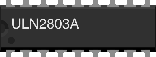
 Design with ULN2803A in Cirkit Designer
Introduction
The ULN2803A is an octal high-voltage, high-current Darlington transistor array. It consists of eight NPN Darlington pairs, each capable of driving high-current loads up to 500 mA per channel, with a maximum voltage rating of 50V. This component is widely used to interface low-level logic signals, such as those from microcontrollers, with high-power devices like relays, lamps, motors, and solenoids. Its built-in freewheeling diodes make it ideal for driving inductive loads.
Explore Projects Built with ULN2803A
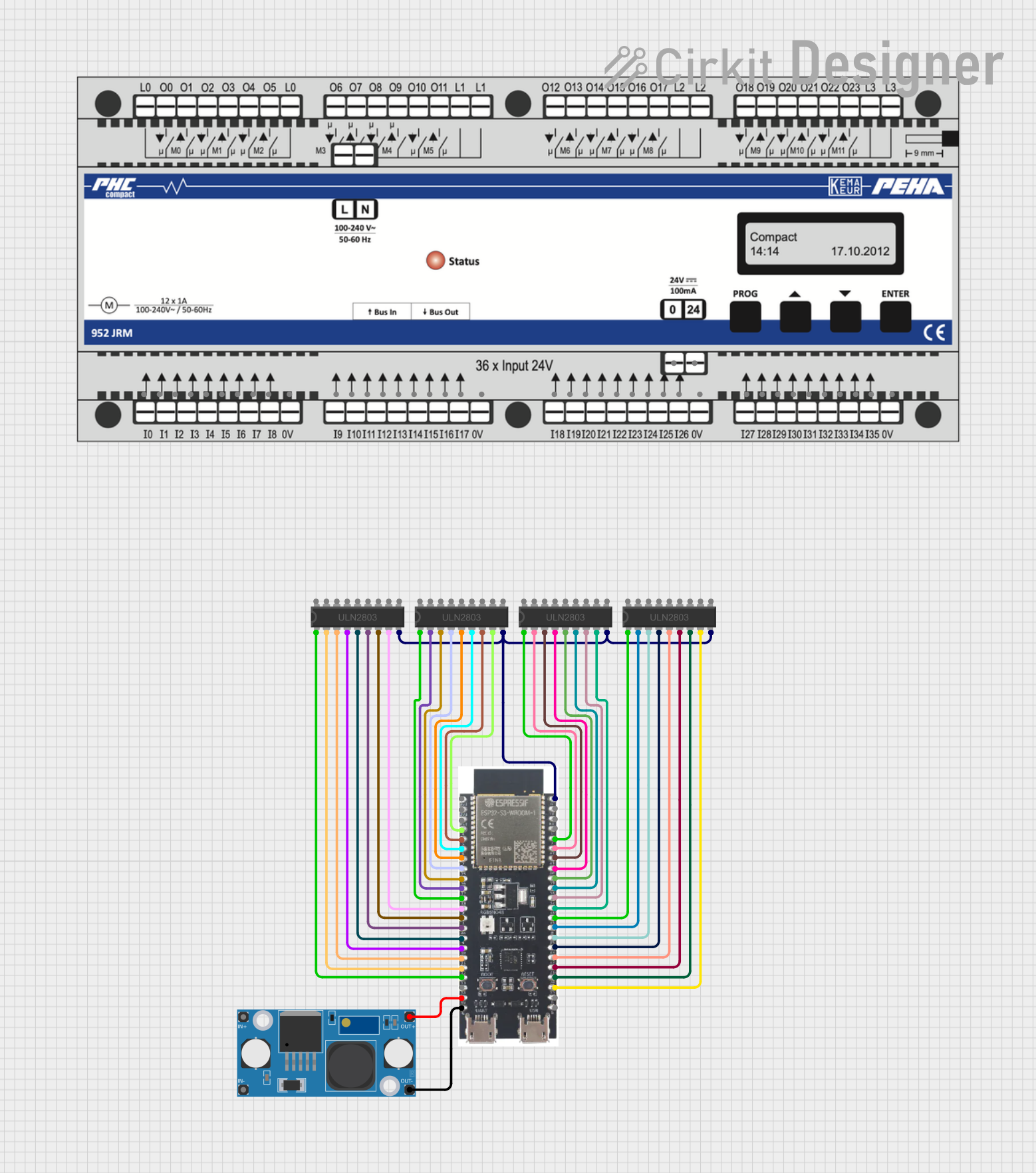 Open Project in Cirkit Designer
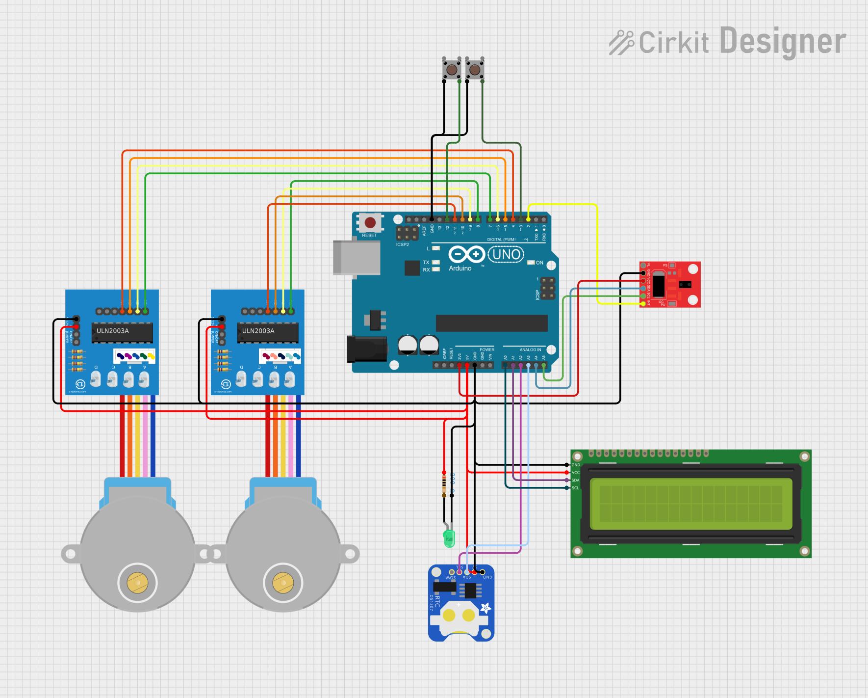 Open Project in Cirkit Designer
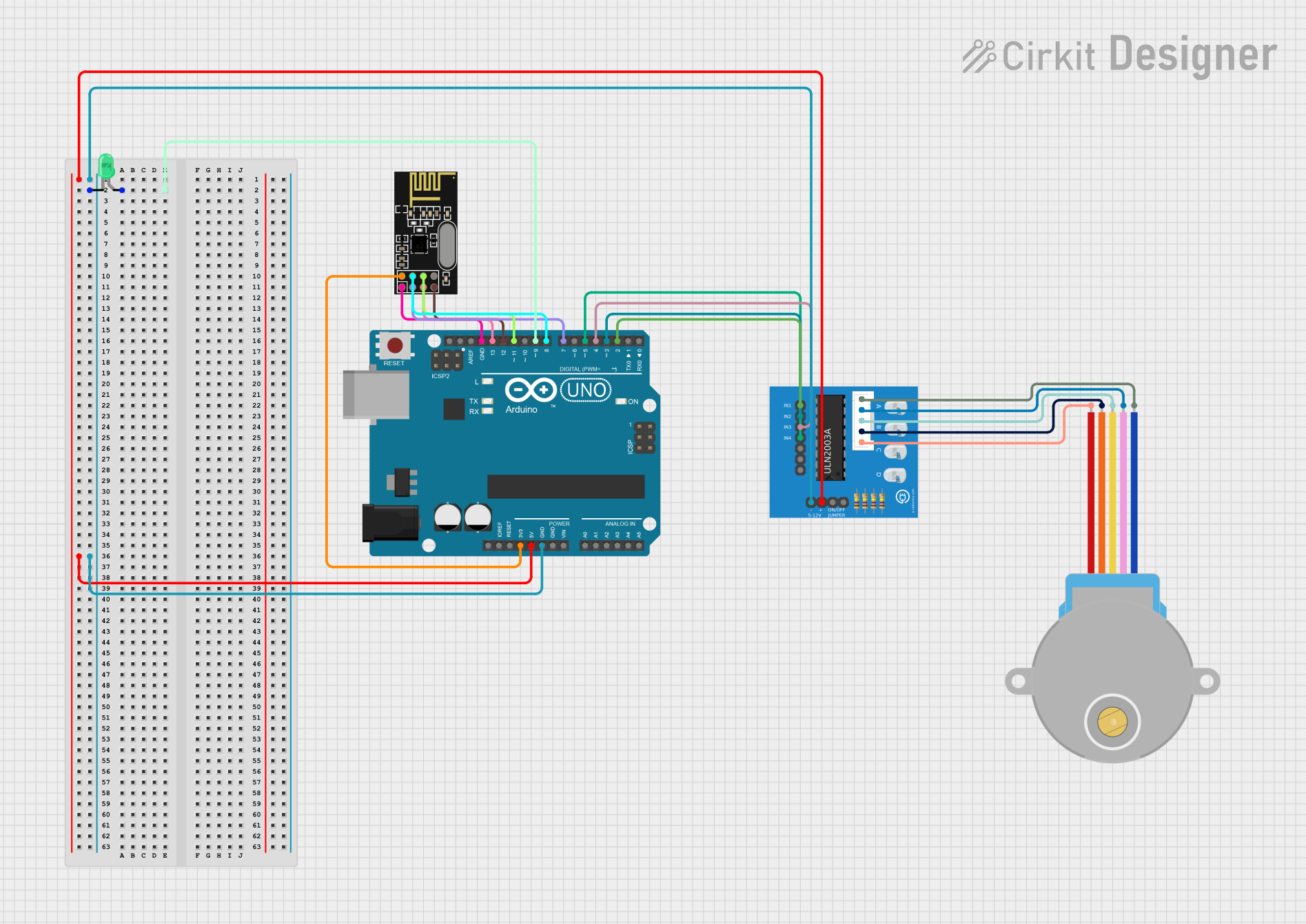 Open Project in Cirkit Designer
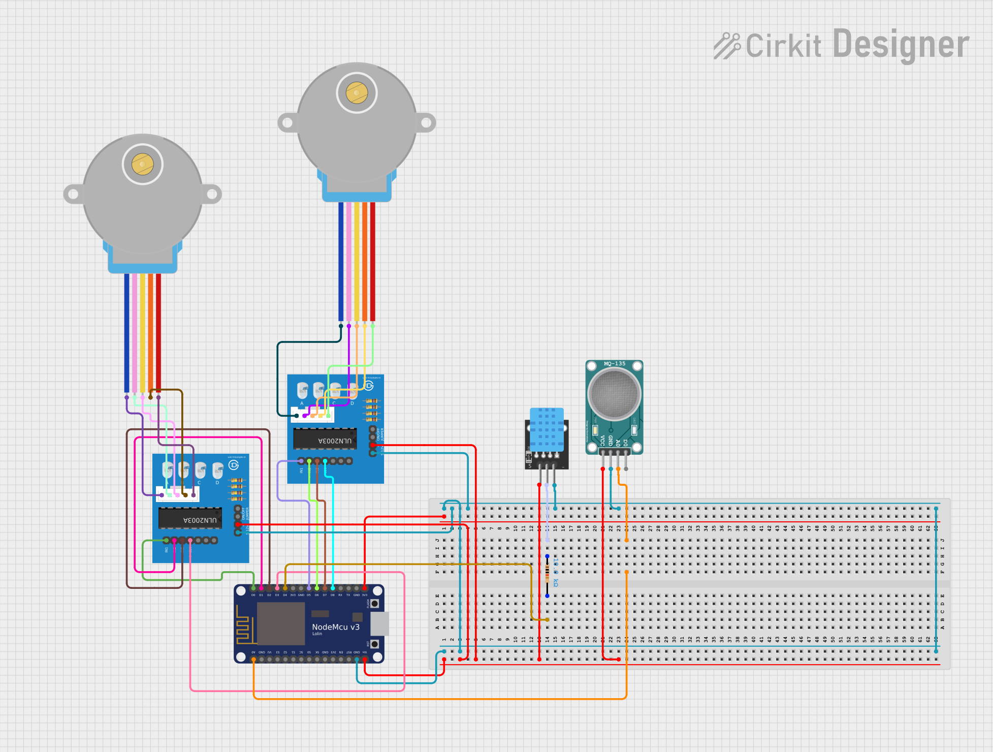 Open Project in Cirkit Designer
Explore Projects Built with ULN2803A
Open Project in Cirkit DesignerOpen Project in Cirkit DesignerOpen Project in Cirkit DesignerOpen Project in Cirkit DesignerCommon Applications
- Driving relays in automation systems
- Controlling stepper motors
- Powering LED arrays
- Interfacing microcontrollers with high-power devices
- Driving solenoids in industrial applications
Technical Specifications
The ULN2803A is designed to simplify the control of high-power devices by providing a robust interface between logic-level signals and high-current loads.
Key Specifications
| Parameter | Value |
|---|---|
| Supply Voltage (Vce) | Up to 50V |
| Output Current (Ic) | 500 mA per channel (max) |
| Input Voltage (Vin) | 5V to 12V (logic-level input) |
| Number of Channels | 8 |
| Input Current (Iin) | 0.93 mA (typical per channel) |
| Built-in Diodes | Yes (for inductive load protection) |
| Package Type | DIP-18, SOIC-18 |
| Operating Temperature | -20°C to 85°C |
Pin Configuration
The ULN2803A has 18 pins, with 8 input pins, 8 output pins, and 2 common pins.
| Pin Number | Name | Description |
|---|---|---|
| 1-8 | IN1-IN8 | Input pins for channels 1 to 8 |
| 9 | COM | Common pin for freewheeling diodes (connect to load supply voltage) |
| 10-17 | OUT1-OUT8 | Output pins for channels 1 to 8 |
| 18 | GND | Ground pin |
Usage Instructions
The ULN2803A is straightforward to use in circuits. Follow these steps to integrate it into your design:
Basic Circuit Connection
- Power Supply: Connect the ground pin (GND) to the ground of your circuit. The common pin (COM) should be connected to the positive supply voltage of the load (e.g., 12V for relays or motors).
- Inputs: Connect the input pins (IN1-IN8) to the logic-level signals from your microcontroller or other control circuitry.
- Outputs: Connect the output pins (OUT1-OUT8) to the negative terminals of your loads (e.g., relays, motors, or LEDs). The positive terminals of the loads should be connected to the supply voltage.
- Inductive Loads: For inductive loads like relays or motors, the built-in freewheeling diodes protect the circuit from voltage spikes.
Example: Driving a Relay with Arduino UNO
Below is an example of how to use the ULN2803A to drive a relay using an Arduino UNO.
Circuit Diagram
- Connect the Arduino digital pin (e.g., D2) to IN1 of the ULN2803A.
- Connect OUT1 to the negative terminal of the relay.
- Connect the positive terminal of the relay to a 12V power supply.
- Connect the COM pin of the ULN2803A to the 12V power supply.
- Connect the GND pin of the ULN2803A to the Arduino GND.
Arduino Code
// Example code to control a relay using ULN2803A and Arduino UNO

#define RELAY_PIN 2  // Define the Arduino pin connected to ULN2803A IN1

void setup() {
  pinMode(RELAY_PIN, OUTPUT);  // Set the relay pin as an output
}

void loop() {
  digitalWrite(RELAY_PIN, HIGH);  // Turn the relay ON
  delay(1000);                    // Wait for 1 second
  digitalWrite(RELAY_PIN, LOW);   // Turn the relay OFF
  delay(1000);                    // Wait for 1 second
}
Best Practices
- Always connect the COM pin to the load's supply voltage to ensure proper operation of the freewheeling diodes.
- Do not exceed the maximum current rating of 500 mA per channel or the total package power dissipation.
- Use a heat sink or proper ventilation if driving multiple high-current loads simultaneously.
- For logic-level inputs, ensure the input voltage is within the specified range (5V to 12V).
Troubleshooting and FAQs
Common Issues
Load Not Turning On
- Cause: Incorrect wiring or insufficient input voltage.
- Solution: Verify the input and output connections. Ensure the input voltage is within the specified range.
Excessive Heat
- Cause: Exceeding the current rating or inadequate ventilation.
- Solution: Reduce the load current or add a heat sink to dissipate heat.
Voltage Spikes
- Cause: Inductive loads without proper diode protection.
- Solution: Ensure the COM pin is connected to the load's supply voltage to activate the built-in freewheeling diodes.
No Output Signal
- Cause: Faulty input signal or damaged component.
- Solution: Check the input signal with a multimeter or oscilloscope. Replace the ULN2803A if necessary.
FAQs
Q1: Can the ULN2803A drive a stepper motor?
Yes, the ULN2803A can drive stepper motors by controlling each coil through its output channels. Ensure the current and voltage ratings of the motor are within the ULN2803A's limits.
Q2: Can I use the ULN2803A with a 3.3V microcontroller?
The ULN2803A is optimized for 5V logic levels. While it may work with 3.3V signals, the input current may not be sufficient to fully saturate the Darlington pairs. Consider using a level shifter or a different driver IC for 3.3V systems.
Q3: What is the purpose of the COM pin?
The COM pin is connected to the load's supply voltage and is used to activate the built-in freewheeling diodes, which protect the circuit from voltage spikes generated by inductive loads.
Q4: Can I leave unused channels unconnected?
Yes, unused input and output pins can be left unconnected without affecting the operation of the other channels.
By following this documentation, you can effectively use the ULN2803A in your projects to drive high-power loads with ease and reliability.