Cirkit Designer Logo
Cirkit Designer
Your all-in-one circuit design IDE
Home / 
Component Documentation

How to Use EC Board v1.1: Examples, Pinouts, and Specs

Image of EC Board v1.1
Cirkit Designer LogoDesign with EC Board v1.1 in Cirkit Designer

Introduction

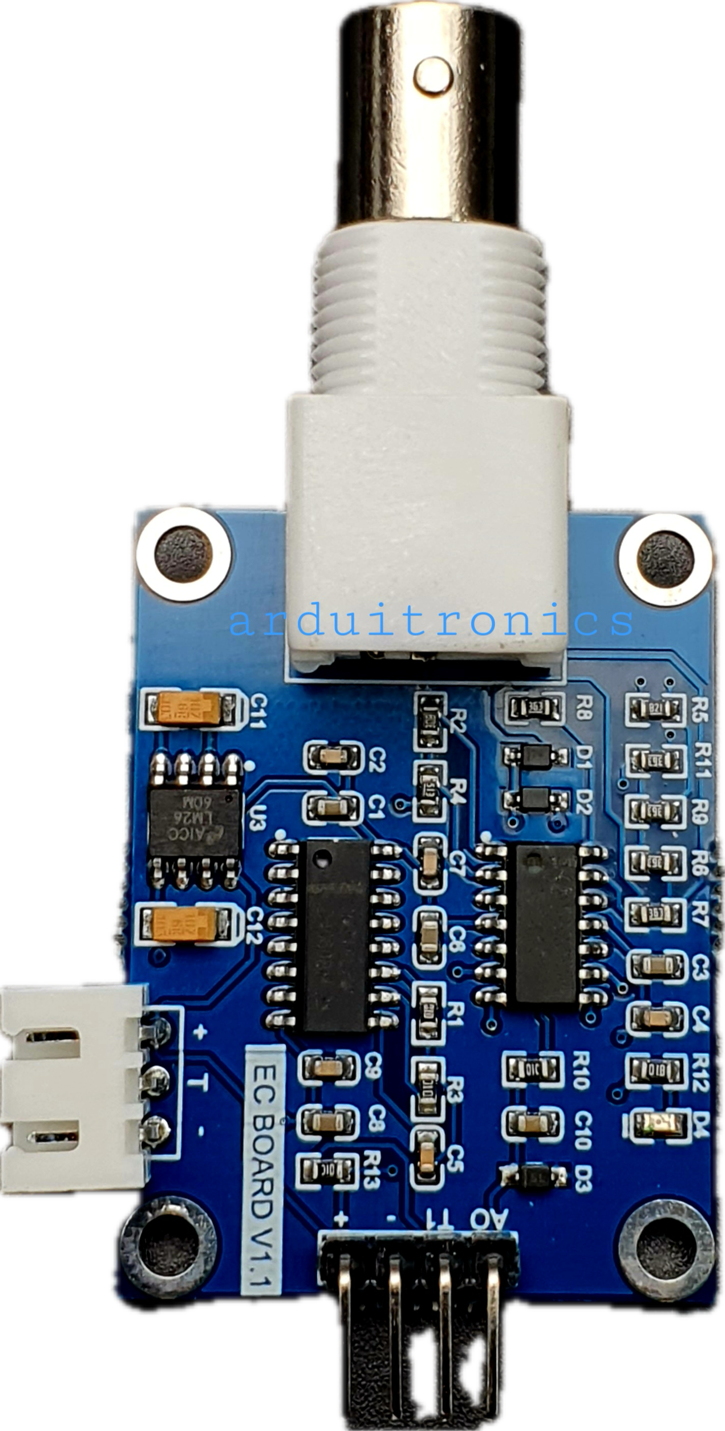
The EC Board v1.1, manufactured by Arduitronics (Part ID: AS10323), is a versatile electronic circuit board designed for prototyping and development. It provides multiple input/output (I/O) ports, power supply connections, and compatibility with a wide range of sensors and modules. This makes it an excellent choice for educational purposes, experimental projects, and rapid prototyping.

Explore Projects Built with EC Board v1.1

Use Cirkit Designer to design, explore, and prototype these projects online. Some projects support real-time simulation. Click "Open Project" to start designing instantly!
Battery-Powered FPV Drone with Telemetry and Dual Motor Control
Image of Krul': A project utilizing EC Board v1.1 in a practical application
This circuit appears to be a power distribution and control system for a vehicle with two motorized wheels, possibly a drone or a robot. It includes a lipo battery connected to a Power Distribution Board (PDB) that distributes power to two Electronic Speed Controllers (ESCs) which in turn control the speed and direction of the motors. The system also integrates a flight controller (H743-SLIM V3) for managing various peripherals including GPS, FPV camera system, and a telemetry link (ExpressLRS).
Cirkit Designer LogoOpen Project in Cirkit Designer
ESP32-Based Vibration Motor Controller with I2C IO Expansion
Image of VIBRATYION: A project utilizing EC Board v1.1 in a practical application
This circuit features an ESP32 Wroom Dev Kit microcontroller interfaced with an MCP23017 I/O expansion board via I2C communication, utilizing GPIO 21 and GPIO 22 for SDA and SCL lines, respectively. A vibration motor is controlled by an NPN transistor acting as a switch, with a diode for back EMF protection and a resistor to limit base current. The ESP32 can control the motor by sending signals to the MCP23017, which then interfaces with the transistor to turn the motor on or off.
Cirkit Designer LogoOpen Project in Cirkit Designer
ESP32 and Logic Level Converter-Based Wi-Fi Controlled Interface
Image of Toshiba AC ESP32 devkit v1: A project utilizing EC Board v1.1 in a practical application
This circuit features an ESP32 Devkit V1 microcontroller connected to a Bi-Directional Logic Level Converter, which facilitates voltage level shifting between the ESP32 and external components. The ESP32 is powered through its VIN pin via an alligator clip cable, and the logic level converter is connected to various pins on the ESP32 to manage different voltage levels for communication.
Cirkit Designer LogoOpen Project in Cirkit Designer
ESP32-Based Wi-Fi Controlled Motor System with ADXL345 Accelerometer
Image of Rangkaian Alat Peraga Crank Rocker Wiper: A project utilizing EC Board v1.1 in a practical application
This circuit features an ESP32 microcontroller interfaced with an ADXL345 accelerometer and a DC motor controlled via an L293 motor driver. It also includes a bi-directional logic level converter for signal compatibility and two rotary encoders for position feedback, all powered by a 12V power supply.
Cirkit Designer LogoOpen Project in Cirkit Designer

Explore Projects Built with EC Board v1.1

Use Cirkit Designer to design, explore, and prototype these projects online. Some projects support real-time simulation. Click "Open Project" to start designing instantly!
Image of Krul': A project utilizing EC Board v1.1 in a practical application
Battery-Powered FPV Drone with Telemetry and Dual Motor Control
This circuit appears to be a power distribution and control system for a vehicle with two motorized wheels, possibly a drone or a robot. It includes a lipo battery connected to a Power Distribution Board (PDB) that distributes power to two Electronic Speed Controllers (ESCs) which in turn control the speed and direction of the motors. The system also integrates a flight controller (H743-SLIM V3) for managing various peripherals including GPS, FPV camera system, and a telemetry link (ExpressLRS).
Cirkit Designer LogoOpen Project in Cirkit Designer
Image of VIBRATYION: A project utilizing EC Board v1.1 in a practical application
ESP32-Based Vibration Motor Controller with I2C IO Expansion
This circuit features an ESP32 Wroom Dev Kit microcontroller interfaced with an MCP23017 I/O expansion board via I2C communication, utilizing GPIO 21 and GPIO 22 for SDA and SCL lines, respectively. A vibration motor is controlled by an NPN transistor acting as a switch, with a diode for back EMF protection and a resistor to limit base current. The ESP32 can control the motor by sending signals to the MCP23017, which then interfaces with the transistor to turn the motor on or off.
Cirkit Designer LogoOpen Project in Cirkit Designer
Image of Toshiba AC ESP32 devkit v1: A project utilizing EC Board v1.1 in a practical application
ESP32 and Logic Level Converter-Based Wi-Fi Controlled Interface
This circuit features an ESP32 Devkit V1 microcontroller connected to a Bi-Directional Logic Level Converter, which facilitates voltage level shifting between the ESP32 and external components. The ESP32 is powered through its VIN pin via an alligator clip cable, and the logic level converter is connected to various pins on the ESP32 to manage different voltage levels for communication.
Cirkit Designer LogoOpen Project in Cirkit Designer
Image of Rangkaian Alat Peraga Crank Rocker Wiper: A project utilizing EC Board v1.1 in a practical application
ESP32-Based Wi-Fi Controlled Motor System with ADXL345 Accelerometer
This circuit features an ESP32 microcontroller interfaced with an ADXL345 accelerometer and a DC motor controlled via an L293 motor driver. It also includes a bi-directional logic level converter for signal compatibility and two rotary encoders for position feedback, all powered by a 12V power supply.
Cirkit Designer LogoOpen Project in Cirkit Designer

Common Applications and Use Cases

  • Educational projects for learning electronics and programming
  • Rapid prototyping of circuits and embedded systems
  • Integration with sensors and actuators for IoT applications
  • Development of small-scale automation systems
  • Experimentation with Arduino and other microcontroller platforms

Technical Specifications

The EC Board v1.1 is designed to simplify circuit development while offering robust functionality. Below are its key technical specifications:

General Specifications

Parameter Value
Manufacturer Arduitronics
Part ID AS10323
Operating Voltage 5V DC
Input Voltage Range 7V–12V DC (via barrel jack)
Maximum Current Output 1A
Dimensions 80mm x 60mm
Weight 50g

Pin Configuration and Descriptions

The EC Board v1.1 features a variety of pins for connecting sensors, modules, and other components. Below is the pin configuration:

Power Pins

Pin Name Description
VIN Input voltage (7V–12V DC)
GND Ground connection
5V Regulated 5V output for powering components
3.3V Regulated 3.3V output for low-power devices

I/O Pins

Pin Name Description
D0–D13 Digital I/O pins (can be used as input/output)
A0–A5 Analog input pins (10-bit resolution)
PWM Pins D3, D5, D6, D9, D10, D11 (PWM output capable)

Communication Pins

Pin Name Description
TX (D1) UART Transmit
RX (D0) UART Receive
SDA I2C Data Line
SCL I2C Clock Line

Usage Instructions

The EC Board v1.1 is designed for ease of use, especially for beginners. Follow the steps below to get started:

Connecting the Board

  1. Power Supply: Connect a 7V–12V DC power source to the VIN pin or the barrel jack. Alternatively, you can power the board via USB if connected to a microcontroller like Arduino.
  2. Peripheral Connections: Attach sensors, modules, or other components to the appropriate I/O pins. Use the 5V or 3.3V pins to power your peripherals.

Using with an Arduino UNO

The EC Board v1.1 is fully compatible with the Arduino UNO. Below is an example of how to use the board to read an analog sensor and control an LED:

Example Code

// Example: Reading an analog sensor and controlling an LED
// Connect the sensor to A0 and the LED to D9

const int sensorPin = A0;  // Analog pin connected to the sensor
const int ledPin = 9;      // Digital pin connected to the LED

void setup() {
  pinMode(ledPin, OUTPUT);  // Set the LED pin as an output
  Serial.begin(9600);       // Initialize serial communication
}

void loop() {
  int sensorValue = analogRead(sensorPin);  // Read the sensor value
  Serial.println(sensorValue);             // Print the value to the Serial Monitor

  // Map the sensor value (0-1023) to PWM range (0-255)
  int ledBrightness = map(sensorValue, 0, 1023, 0, 255);
  analogWrite(ledPin, ledBrightness);      // Set the LED brightness

  delay(100);  // Wait for 100ms before the next reading
}

Important Considerations

  • Voltage Levels: Ensure that connected components operate within the board's voltage range (5V or 3.3V).
  • Current Limits: Do not exceed the maximum current output of 1A to avoid damaging the board.
  • Pin Usage: Avoid using the same pin for multiple functions simultaneously (e.g., digital I/O and PWM).

Troubleshooting and FAQs

Common Issues

  1. Board Not Powering On

    • Cause: Insufficient input voltage or loose connections.
    • Solution: Ensure the input voltage is within the 7V–12V range and check all connections.
  2. Components Not Responding

    • Cause: Incorrect pin connections or mismatched voltage levels.
    • Solution: Verify the wiring and ensure the components are compatible with the board's voltage.
  3. Serial Communication Not Working

    • Cause: Incorrect baud rate or TX/RX pin usage.
    • Solution: Match the baud rate in your code with the Serial Monitor and ensure TX/RX pins are correctly connected.

FAQs

Q: Can I power the board using a USB connection?
A: Yes, the board can be powered via USB when connected to a microcontroller like Arduino.

Q: Is the EC Board v1.1 compatible with 3.3V sensors?
A: Yes, the board provides a 3.3V output pin for low-power devices.

Q: Can I use all the digital pins for PWM?
A: No, only specific pins (D3, D5, D6, D9, D10, D11) support PWM output.

By following this documentation, you can effectively use the EC Board v1.1 for your projects and experiments.