How to Use PCM1822IRTER: Examples, Pinouts, and Specs
Introduction
The PCM1822IRTER is a high-performance, low-power stereo analog-to-digital converter (ADC) manufactured by Texas Instruments. It is designed specifically for audio applications, offering a 24-bit resolution and supporting sampling rates of up to 192 kHz. This makes it ideal for high-fidelity audio processing in consumer electronics, professional audio equipment, and other audio systems.
The PCM1822IRTER integrates advanced digital filters and a flexible digital audio interface, simplifying its integration into a wide range of audio designs. Its low power consumption and compact size make it suitable for portable and space-constrained applications.
Explore Projects Built with PCM1822IRTER
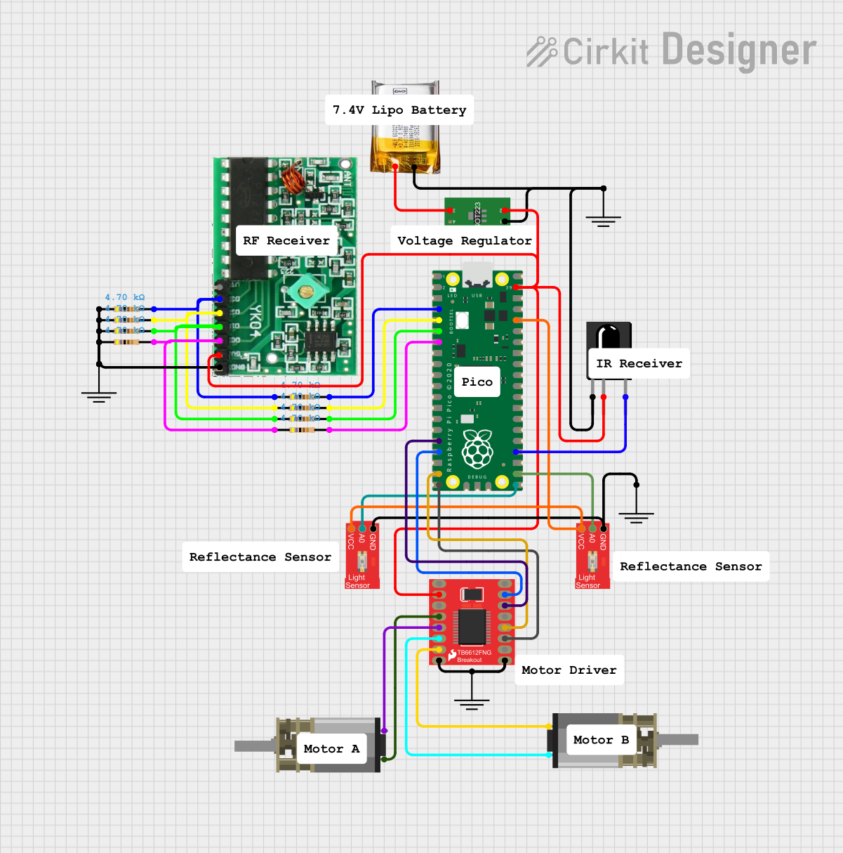
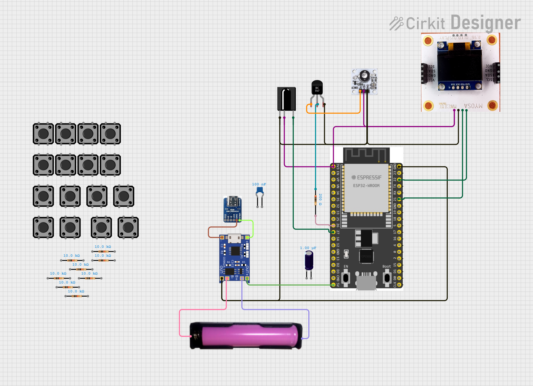
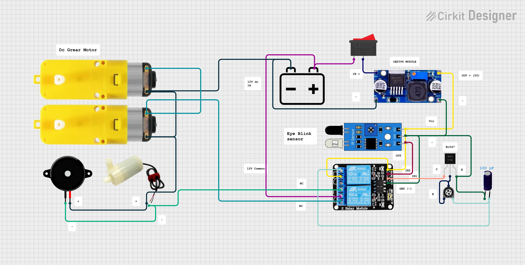
Explore Projects Built with PCM1822IRTER
Common Applications
- Audio recording devices
- Professional audio equipment
- Consumer electronics (e.g., TVs, soundbars, and home theater systems)
- Voice recognition systems
- Musical instruments and audio effects processors
Technical Specifications
Key Technical Details
| Parameter | Value |
|---|---|
| Resolution | 24-bit |
| Sampling Rate | Up to 192 kHz |
| Input Channels | 2 (Stereo) |
| Analog Input Type | Differential or Single-Ended |
| Signal-to-Noise Ratio (SNR) | 103 dB (typical) |
| Total Harmonic Distortion + Noise (THD+N) | -93 dB (typical) |
| Power Supply Voltage | 3.3 V (Digital), 3.3 V or 5 V (Analog) |
| Power Consumption | 14 mW (typical, at 3.3 V) |
| Digital Audio Interface | I²S, Left-Justified, or TDM |
| Package Type | 16-pin WQFN (RTE) |
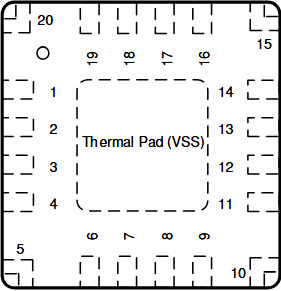
Pin Configuration and Descriptions
The PCM1822IRTER is available in a 16-pin WQFN package. Below is the pinout and description:
| Pin No. | Name | Type | Description |
|---|---|---|---|
| 1 | VREF | Analog | Reference voltage for ADC |
| 2 | VINL+ | Analog | Positive input for left channel |
| 3 | VINL- | Analog | Negative input for left channel |
| 4 | VINR+ | Analog | Positive input for right channel |
| 5 | VINR- | Analog | Negative input for right channel |
| 6 | GND | Ground | Ground connection |
| 7 | VDD | Power | Digital power supply (3.3 V) |
| 8 | LRCK | Digital I/O | Left/Right clock for I²S or TDM interface |
| 9 | BCK | Digital I/O | Bit clock for I²S or TDM interface |
| 10 | DIN | Digital I/O | Data input for TDM mode |
| 11 | DOUT | Digital O | Data output for I²S or TDM interface |
| 12 | SCK | Digital I | System clock input |
| 13 | SDA | Digital I/O | I²C data line |
| 14 | SCL | Digital I | I²C clock line |
| 15 | RESET | Digital I | Active-low reset input |
| 16 | VCCA | Power | Analog power supply (3.3 V or 5 V) |
Usage Instructions
How to Use the PCM1822IRTER in a Circuit
- Power Supply: Connect the digital power supply (VDD) to 3.3 V and the analog power supply (VCCA) to either 3.3 V or 5 V, depending on your design requirements. Ensure proper decoupling capacitors are placed near the power pins.
- Analog Inputs: Connect the audio signal to the differential or single-ended input pins (VINL+, VINL-, VINR+, VINR-). Use appropriate coupling capacitors to block DC components.
- Clock Configuration: Provide a stable system clock (SCK) to the device. The clock frequency should match the desired sampling rate and audio interface configuration.
- Digital Audio Interface: Configure the I²S, Left-Justified, or TDM interface using the LRCK, BCK, and DOUT pins. Ensure the host processor or microcontroller is configured to match the PCM1822IRTER's audio format.
- I²C Communication: Use the SDA and SCL pins to configure the device via the I²C interface. This allows you to set parameters such as sampling rate, input gain, and digital filter options.
- Reset: Use the RESET pin to initialize the device during power-up or after a fault condition.
Important Considerations and Best Practices
- Grounding: Ensure a solid ground plane to minimize noise and interference.
- Decoupling: Place decoupling capacitors (e.g., 0.1 µF and 10 µF) close to the power supply pins to ensure stable operation.
- Input Impedance: Match the input impedance of the ADC to the source impedance for optimal performance.
- Clock Jitter: Minimize clock jitter to maintain high audio quality.
- Thermal Management: Although the PCM1822IRTER has low power consumption, ensure adequate thermal dissipation in high-temperature environments.
Example: Connecting PCM1822IRTER to an Arduino UNO
Below is an example of how to interface the PCM1822IRTER with an Arduino UNO using the I²C interface:
#include <Wire.h> // Include the Wire library for I²C communication

#define PCM1822_I2C_ADDRESS 0x4C // Default I²C address of PCM1822IRTER

void setup() {
  Wire.begin(); // Initialize I²C communication
  Serial.begin(9600); // Initialize serial communication for debugging

  // Reset the PCM1822IRTER
  pinMode(7, OUTPUT); // Assume RESET pin is connected to Arduino pin 7
  digitalWrite(7, LOW); // Hold RESET low
  delay(10); // Wait for 10 ms
  digitalWrite(7, HIGH); // Release RESET
  delay(10); // Wait for the device to initialize

  // Configure the PCM1822IRTER via I²C
  Wire.beginTransmission(PCM1822_I2C_ADDRESS);
  Wire.write(0x00); // Write to a configuration register (example)
  Wire.write(0x01); // Example value to configure the device
  Wire.endTransmission();

  Serial.println("PCM1822IRTER initialized.");
}

void loop() {
  // Main loop can handle audio data processing
}
Troubleshooting and FAQs
Common Issues and Solutions
No Output Signal:
- Ensure the system clock (SCK) is stable and matches the required frequency.
- Verify that the RESET pin is properly initialized during startup.
- Check the I²C configuration to ensure the device is correctly set up.
Distorted Audio:
- Verify that the input signal levels do not exceed the maximum input range of the ADC.
- Check for proper grounding and minimize noise in the analog input path.
- Ensure the clock jitter is within acceptable limits.
I²C Communication Failure:
- Confirm the I²C address of the PCM1822IRTER matches the address used in the code.
- Check the pull-up resistors on the SDA and SCL lines.
High Noise or Low SNR:
- Ensure proper decoupling capacitors are used on the power supply pins.
- Verify that the input impedance matches the source impedance.
FAQs
Q: Can the PCM1822IRTER operate with a single-ended input?
A: Yes, the PCM1822IRTER supports both differential and single-ended inputs. For single-ended operation, connect the negative input pin (e.g., VINL-) to ground.
Q: What is the maximum sampling rate supported?
A: The PCM1822IRTER supports sampling rates of up to 192 kHz.
Q: Does the PCM1822IRTER require an external clock source?
A: Yes, the device requires a stable system clock (SCK) for proper operation. The clock frequency should match the desired sampling rate and audio interface configuration.
Q: Can the PCM1822IRTER be used in battery-powered devices?
A: Yes, its low power consumption (14 mW typical) makes it suitable for battery-powered applications.
This concludes the documentation for the PCM1822IRTER. For further details, refer to the official Texas Instruments datasheet.