How to Use ESP32: Examples, Pinouts, and Specs
Introduction
The ESP32, manufactured by Arduino with the part ID UNO, is a low-cost, low-power system on a chip (SoC) that integrates Wi-Fi and Bluetooth capabilities. It is widely recognized for its versatility and performance, making it a popular choice for Internet of Things (IoT) applications. The ESP32 is designed to handle a wide range of tasks, from simple sensor monitoring to complex data processing and wireless communication.
Explore Projects Built with ESP32


Explore Projects Built with ESP32
Common Applications and Use Cases
- IoT devices and smart home automation
- Wireless sensor networks
- Wearable electronics
- Industrial automation
- Robotics and drones
- Real-time data logging and monitoring
Technical Specifications
The ESP32 is a powerful and feature-rich microcontroller. Below are its key technical specifications:
General Specifications
| Feature | Specification |
|---|---|
| Manufacturer | Arduino |
| Part ID | UNO |
| Processor | Dual-core Xtensa LX6 @ 240 MHz |
| Flash Memory | Up to 16 MB |
| SRAM | 520 KB |
| Wireless Connectivity | Wi-Fi 802.11 b/g/n, Bluetooth 4.2 |
| Operating Voltage | 3.3V |
| GPIO Pins | 34 |
| ADC Channels | 18 |
| DAC Channels | 2 |
| Communication Interfaces | UART, SPI, I2C, I2S, CAN, PWM |
| Power Consumption | Ultra-low power (varies by mode) |
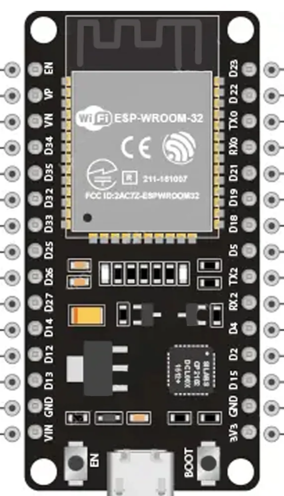
Pin Configuration and Descriptions
The ESP32 has a total of 38 pins, with 34 GPIO pins. Below is a table summarizing the key pin functions:
| Pin Number | Pin Name | Description |
|---|---|---|
| 1 | EN | Enable pin (active high) |
| 2 | IO0 | GPIO0, used for boot mode selection |
| 3 | IO1 (TX0) | GPIO1, UART0 TX |
| 4 | IO3 (RX0) | GPIO3, UART0 RX |
| 5 | IO4 | GPIO4, PWM, ADC, or DAC |
| 6-11 | IO12-IO15 | GPIO pins with ADC and PWM capabilities |
| 12 | IO16 | GPIO16, used for deep sleep wake-up |
| 13 | IO17 | GPIO17, UART2 TX |
| 14 | IO18 | GPIO18, SPI CLK |
| 15 | IO19 | GPIO19, SPI MISO |
| 16 | IO21 | GPIO21, I2C SDA |
| 17 | IO22 | GPIO22, I2C SCL |
| 18 | IO23 | GPIO23, SPI MOSI |
| 19 | IO25 | GPIO25, DAC1 |
| 20 | IO26 | GPIO26, DAC2 |
| 21 | IO27 | GPIO27, ADC, PWM |
| 22 | IO32-IO39 | GPIO pins with ADC capabilities |
Note: Some GPIO pins have specific restrictions or are used during boot. Refer to the ESP32 datasheet for detailed pin behavior.
Usage Instructions
The ESP32 can be used in a variety of circuits and applications. Below are the steps to get started:
Connecting the ESP32 to an Arduino UNO
- Power Supply: Ensure the ESP32 is powered with 3.3V. Do not connect it directly to 5V as it may damage the chip.
- Serial Communication: Use the UART pins (TX and RX) to communicate with the Arduino UNO. Use a voltage divider or level shifter to match voltage levels.
- Programming: The ESP32 can be programmed using the Arduino IDE. Install the ESP32 board package in the Arduino IDE via the Board Manager.
Example Code: Blink an LED
The following example demonstrates how to blink an LED connected to GPIO2 of the ESP32:
// Blink an LED connected to GPIO2 on the ESP32
// Ensure the LED's anode is connected to GPIO2 and cathode to GND

#define LED_PIN 2  // Define the GPIO pin for the LED

void setup() {
  pinMode(LED_PIN, OUTPUT);  // Set GPIO2 as an output pin
}

void loop() {
  digitalWrite(LED_PIN, HIGH);  // Turn the LED on
  delay(1000);                  // Wait for 1 second
  digitalWrite(LED_PIN, LOW);   // Turn the LED off
  delay(1000);                  // Wait for 1 second
}
Important Considerations
- Voltage Levels: The ESP32 operates at 3.3V. Ensure all connected peripherals are compatible with this voltage.
- Boot Mode: GPIO0 must be pulled low during boot to enter programming mode.
- Power Consumption: Use deep sleep mode to minimize power consumption in battery-powered applications.
Troubleshooting and FAQs
Common Issues
ESP32 Not Detected in Arduino IDE
- Ensure the correct board and port are selected in the Arduino IDE.
- Install the ESP32 board package via the Board Manager.
Upload Fails with "Failed to Connect" Error
- Hold the BOOT button on the ESP32 while uploading the code.
- Check the USB cable and ensure it supports data transfer.
Wi-Fi Connection Issues
- Verify the SSID and password in your code.
- Ensure the router is within range and supports 2.4 GHz Wi-Fi.
GPIO Pin Not Working
- Check if the pin is used for boot or other special functions.
- Avoid using GPIO6-GPIO11 as they are connected to the internal flash.
Tips for Troubleshooting
- Use a multimeter to verify power supply voltage.
- Check serial monitor output for error messages.
- Refer to the ESP32 datasheet for detailed pin and peripheral information.
By following this documentation, users can effectively utilize the ESP32 in their projects and troubleshoot common issues with ease.