How to Use WS2812B LED: Examples, Pinouts, and Specs
Introduction
The WS2812B LED is a smart RGB LED that integrates a control circuit and RGB chip into a single package. This design allows for individually addressable color control and brightness, making it a popular choice for dynamic lighting projects. Each LED can display a full spectrum of colors and is controlled via a single data line, simplifying wiring and reducing the number of required microcontroller pins.
Explore Projects Built with WS2812B LED

Explore Projects Built with WS2812B LED
Common Applications and Use Cases
- LED strips for decorative and architectural lighting
- Wearable electronics and costumes
- Digital displays and signage
- Interactive art installations
- DIY projects and hobbyist electronics
Technical Specifications
Key Technical Details
- Operating Voltage: 3.5V to 5.3V (typically 5V)
- Current Consumption: ~20mA per color channel (60mA max per LED at full brightness)
- Communication Protocol: Single-wire serial (timing-based)
- LED Type: RGB (Red, Green, Blue)
- Brightness Control: 8-bit PWM per channel (24-bit color depth)
- Data Transfer Rate: Up to 800kbps
- Viewing Angle: ~120 degrees
- Operating Temperature: -25°C to +80°C
Pin Configuration and Descriptions
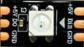
The WS2812B LED typically has 4 pins. Below is the pinout:
| Pin Name | Pin Number | Description |
|---|---|---|
| VDD | 1 | Power supply input (3.5V to 5.3V) |
| GND | 2 | Ground connection |
| DIN | 3 | Data input (control signal from MCU) |
| DOUT | 4 | Data output (to the next LED in series) |
Usage Instructions
How to Use the WS2812B in a Circuit
- Power Supply: Connect the VDD pin to a 5V power source and the GND pin to ground. Ensure the power supply can handle the total current draw of all LEDs in the circuit.
- Data Line: Connect the DIN pin to a microcontroller's digital output pin. Use a resistor (330-500 ohms) in series with the data line to reduce noise and protect the LED.
- Capacitor: Place a 100µF capacitor across the VDD and GND pins to stabilize the power supply.
- Chaining LEDs: To connect multiple LEDs, link the DOUT pin of one LED to the DIN pin of the next. Repeat for all LEDs in the chain.
Important Considerations and Best Practices
- Voltage Level: Ensure the microcontroller's data pin operates at 5V logic levels. If using a 3.3V microcontroller, a level shifter may be required.
- Timing Accuracy: The WS2812B uses precise timing for data communication. Use libraries (e.g., Adafruit NeoPixel) to simplify control.
- Heat Management: Avoid running LEDs at full brightness for extended periods to prevent overheating.
- Data Line Length: Keep the data line as short as possible to avoid signal degradation. For longer distances, consider using a buffer or repeater.
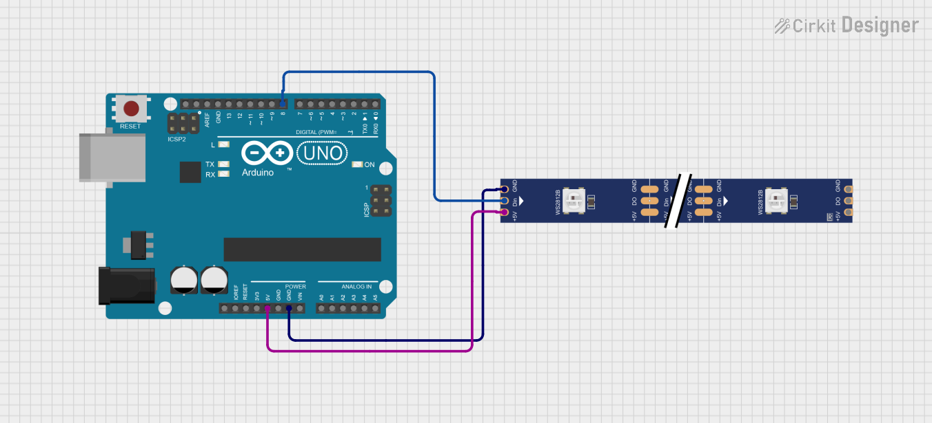
Example Code for Arduino UNO
Below is an example of how to control a WS2812B LED strip using the Adafruit NeoPixel library:
#include <Adafruit_NeoPixel.h>

// Define the pin connected to the DIN pin of the WS2812B
#define LED_PIN 6

// Define the number of LEDs in the strip
#define NUM_LEDS 16

// Create a NeoPixel object
Adafruit_NeoPixel strip = Adafruit_NeoPixel(NUM_LEDS, LED_PIN, NEO_GRB + NEO_KHZ800);

void setup() {
  strip.begin(); // Initialize the NeoPixel library
  strip.show();  // Turn off all LEDs initially
}

void loop() {
  // Set the first LED to red
  strip.setPixelColor(0, strip.Color(255, 0, 0)); // RGB: Red
  strip.show(); // Update the LED strip
  delay(500);   // Wait for 500ms

  // Set the first LED to green
  strip.setPixelColor(0, strip.Color(0, 255, 0)); // RGB: Green
  strip.show(); // Update the LED strip
  delay(500);   // Wait for 500ms

  // Set the first LED to blue
  strip.setPixelColor(0, strip.Color(0, 0, 255)); // RGB: Blue
  strip.show(); // Update the LED strip
  delay(500);   // Wait for 500ms
}
Troubleshooting and FAQs
Common Issues and Solutions
LEDs Not Lighting Up
- Cause: Incorrect wiring or insufficient power supply.
- Solution: Double-check all connections, ensure the power supply voltage is 5V, and verify the data pin is correctly connected.
Flickering or Incorrect Colors
- Cause: Signal degradation or timing issues.
- Solution: Add a resistor (330-500 ohms) in series with the data line, and ensure the microcontroller's timing is accurate. Use a library like Adafruit NeoPixel for reliable control.
Only the First LED Works
- Cause: Data signal not passing to subsequent LEDs.
- Solution: Check the connection between the DOUT pin of one LED and the DIN pin of the next. Ensure the LEDs are powered correctly.
Overheating
- Cause: LEDs running at full brightness for extended periods.
- Solution: Reduce brightness or limit the number of LEDs powered simultaneously.
FAQs
Can I cut a WS2812B LED strip? Yes, you can cut the strip at the marked cut lines. Ensure you reconnect the VDD, GND, and data lines properly.
What is the maximum number of LEDs I can control? Theoretically, there is no limit, but practical constraints like memory and power supply capacity must be considered.
Can I power the LEDs with a 3.7V LiPo battery? While the WS2812B can operate at 3.5V, the brightness may be reduced, and a level shifter may be needed for the data signal.