How to Use Radiator Fan 12V 80W: Examples, Pinouts, and Specs
Introduction
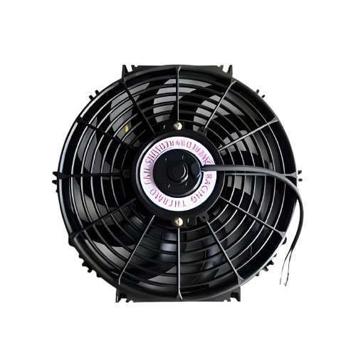
The Radiator Fan 12V 80W is a high-performance cooling device designed to dissipate heat effectively from engines, radiators, or electronic components. Operating at 12 volts and consuming 80 watts of power, this fan provides efficient airflow to maintain optimal operating temperatures in various systems. Its robust design makes it suitable for automotive, industrial, and electronic cooling applications.
Explore Projects Built with Radiator Fan 12V 80W
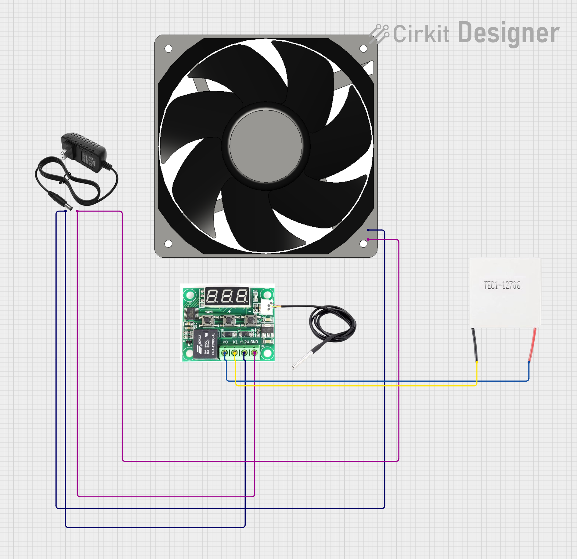
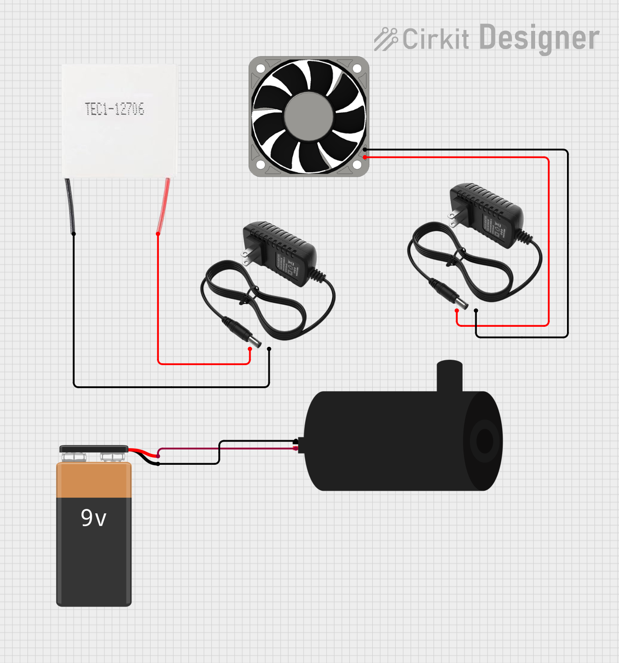


Explore Projects Built with Radiator Fan 12V 80W
Common Applications and Use Cases
- Automotive engine cooling systems
- Cooling for radiators in industrial machinery
- Heat dissipation for high-power electronic components
- Custom PC builds and server cooling
- Renewable energy systems (e.g., solar inverters)
Technical Specifications
Below are the key technical details and pin configuration for the Radiator Fan 12V 80W:
Key Technical Details
| Parameter | Specification |
|---|---|
| Operating Voltage | 12V DC |
| Power Consumption | 80W |
| Current Draw | 6.67A (approx.) |
| Airflow Capacity | 200-300 CFM (varies by model) |
| Fan Speed | 2500-3500 RPM |
| Dimensions | 120mm x 120mm x 25mm |
| Connector Type | 2-pin or 3-pin (varies) |
| Operating Temperature | -20°C to 70°C |
| Noise Level | 30-40 dB (typical) |
| Material | ABS plastic and metal |
Pin Configuration and Descriptions
| Pin Number | Wire Color | Description |
|---|---|---|
| 1 | Red | Positive terminal (+12V DC input) |
| 2 | Black | Ground (GND) |
| 3 (optional) | Yellow | Tachometer signal (RPM feedback) |
Note: The third pin (yellow wire) is optional and may not be present in all models. It is used for monitoring fan speed in systems that support RPM feedback.
Usage Instructions
How to Use the Component in a Circuit
- Power Supply: Ensure a stable 12V DC power source capable of supplying at least 7A to handle the fan's current draw.
- Wiring:
- Connect the red wire to the positive terminal of the power supply.
- Connect the black wire to the ground terminal of the power supply.
- If using the tachometer (yellow wire), connect it to a microcontroller or monitoring system that supports RPM feedback.
- Mounting: Secure the fan to the desired location using screws or brackets. Ensure proper airflow direction by checking the fan's markings (airflow arrows are typically present on the fan housing).
- Testing: Power on the system and verify that the fan operates smoothly without unusual noise or vibration.
Important Considerations and Best Practices
- Power Supply: Use a regulated 12V DC power source to avoid voltage fluctuations that could damage the fan.
- Current Rating: Ensure the power supply can handle the fan's peak current draw (6.67A).
- Airflow Direction: Install the fan in the correct orientation to ensure proper airflow for cooling.
- Noise Management: If noise is a concern, consider using vibration dampeners or fan speed controllers.
- Overheating Protection: Avoid blocking the fan's airflow or operating it in environments exceeding its maximum temperature rating.
Example: Connecting to an Arduino UNO
If you want to control the fan using an Arduino UNO, you can use a transistor or relay module to handle the high current. Below is an example circuit and code:
Circuit Setup
- Connect the fan's red wire to the collector of an NPN transistor (e.g., TIP120).
- Connect the fan's black wire to the ground.
- Connect the emitter of the transistor to the ground.
- Use a 1kΩ resistor to connect the base of the transistor to an Arduino digital pin (e.g., pin 9).
- Connect a 12V DC power supply to the fan's red wire and the Arduino's ground.
Arduino Code
// Define the pin connected to the transistor base
const int fanPin = 9;

void setup() {
  pinMode(fanPin, OUTPUT); // Set the fan control pin as an output
}

void loop() {
  digitalWrite(fanPin, HIGH); // Turn the fan ON
  delay(5000);                // Keep the fan ON for 5 seconds
  digitalWrite(fanPin, LOW);  // Turn the fan OFF
  delay(5000);                // Keep the fan OFF for 5 seconds
}
Note: The transistor acts as a switch to control the fan, as the Arduino cannot directly supply the required current.
Troubleshooting and FAQs
Common Issues and Solutions
| Issue | Possible Cause | Solution |
|---|---|---|
| Fan does not spin | No power or incorrect wiring | Check power supply and wiring |
| Fan spins but airflow is weak | Installed in the wrong orientation | Reinstall with correct airflow direction |
| Excessive noise or vibration | Loose mounting or damaged fan blades | Tighten screws or replace the fan |
| Fan speed not detected | Tachometer wire not connected properly | Verify yellow wire connection |
| Overheating of components | Insufficient airflow or blocked vents | Ensure proper ventilation and airflow |
FAQs
Can I use this fan with a 24V power supply?
- No, this fan is designed for 12V DC operation. Using a higher voltage may damage the fan.
How do I reduce the fan speed?
- Use a PWM controller or a fan speed controller to adjust the voltage or duty cycle.
Can I use this fan in outdoor environments?
- The fan is not waterproof. Use it in a protected environment or choose a weatherproof model for outdoor use.
What happens if the fan draws more current than my power supply can provide?
- The power supply may shut down or overheat. Always use a power supply with sufficient current capacity.
By following this documentation, you can effectively integrate and operate the Radiator Fan 12V 80W in your projects.