Cirkit Designer Logo
Cirkit Designer
Your all-in-one circuit design IDE
Home / 
Component Documentation

How to Use Differential Pressure Sensor: Examples, Pinouts, and Specs

Image of Differential Pressure Sensor
Cirkit Designer LogoDesign with Differential Pressure Sensor in Cirkit Designer

Introduction

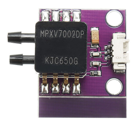
A differential pressure sensor is an electronic device designed to measure the difference in pressure between two points within a fluid flow system. This sensor is crucial in applications where pressure difference is a key parameter, such as HVAC systems, medical instrumentation, and various types of industrial process control. By monitoring differential pressure, these sensors can help ensure systems are operating correctly and efficiently.

Explore Projects Built with Differential Pressure Sensor

Use Cirkit Designer to design, explore, and prototype these projects online. Some projects support real-time simulation. Click "Open Project" to start designing instantly!
ESP32-Controlled Pressure Monitoring System with ADS1115 and Darlington Transistor Switching
Image of Pressuer Sensor Test Rig: A project utilizing Differential Pressure Sensor in a practical application
This circuit is designed to measure pressure using a transducer, convert the analog signal to digital with an ADS1115 ADC, and process and display the data on an ESP32 microcontroller with a 7-inch screen. It includes power regulation and filtering, as well as a Darlington transistor for load control.
Cirkit Designer LogoOpen Project in Cirkit Designer
ESP32 and Arduino Mega 2560 Controlled Peristaltic Pump System with Pressure and Flow Sensors
Image of Blood & Dialysate Control Bench: A project utilizing Differential Pressure Sensor in a practical application
This circuit is designed for fluid control and monitoring, featuring multiple peristaltic pumps driven by TB6600 micro-stepping motor drivers, and pressure sensors interfaced with custom PCBs containing ESP32 microcontrollers. It also includes flow meters connected to Arduino Mega 2560 boards for precise flow rate measurement, with power management handled by DC-DC converters and power supplies.
Cirkit Designer LogoOpen Project in Cirkit Designer
Wi-Fi Enabled Water Monitoring System with ESP8266
Image of Copy of automatic water leak detection: A project utilizing Differential Pressure Sensor in a practical application
This circuit monitors water pressure and flow using a Gravity analog water pressure sensor and a water flow sensor, respectively. The sensors are powered by a 5V adapter and their signals are read by an ESP8266 microcontroller, which can process and transmit the data for further use.
Cirkit Designer LogoOpen Project in Cirkit Designer
Wi-Fi Enabled Water Monitoring System with ESP8266
Image of automatic water leak detection: A project utilizing Differential Pressure Sensor in a practical application
This circuit monitors water pressure and flow using a Gravity analog water pressure sensor and a water flow sensor, respectively. The sensors are powered by a 5V adapter and their signals are read by an ESP8266 microcontroller, which can process and transmit the data for further use.
Cirkit Designer LogoOpen Project in Cirkit Designer

Explore Projects Built with Differential Pressure Sensor

Use Cirkit Designer to design, explore, and prototype these projects online. Some projects support real-time simulation. Click "Open Project" to start designing instantly!
Image of Pressuer Sensor Test Rig: A project utilizing Differential Pressure Sensor in a practical application
ESP32-Controlled Pressure Monitoring System with ADS1115 and Darlington Transistor Switching
This circuit is designed to measure pressure using a transducer, convert the analog signal to digital with an ADS1115 ADC, and process and display the data on an ESP32 microcontroller with a 7-inch screen. It includes power regulation and filtering, as well as a Darlington transistor for load control.
Cirkit Designer LogoOpen Project in Cirkit Designer
Image of Blood & Dialysate Control Bench: A project utilizing Differential Pressure Sensor in a practical application
ESP32 and Arduino Mega 2560 Controlled Peristaltic Pump System with Pressure and Flow Sensors
This circuit is designed for fluid control and monitoring, featuring multiple peristaltic pumps driven by TB6600 micro-stepping motor drivers, and pressure sensors interfaced with custom PCBs containing ESP32 microcontrollers. It also includes flow meters connected to Arduino Mega 2560 boards for precise flow rate measurement, with power management handled by DC-DC converters and power supplies.
Cirkit Designer LogoOpen Project in Cirkit Designer
Image of Copy of automatic water leak detection: A project utilizing Differential Pressure Sensor in a practical application
Wi-Fi Enabled Water Monitoring System with ESP8266
This circuit monitors water pressure and flow using a Gravity analog water pressure sensor and a water flow sensor, respectively. The sensors are powered by a 5V adapter and their signals are read by an ESP8266 microcontroller, which can process and transmit the data for further use.
Cirkit Designer LogoOpen Project in Cirkit Designer
Image of automatic water leak detection: A project utilizing Differential Pressure Sensor in a practical application
Wi-Fi Enabled Water Monitoring System with ESP8266
This circuit monitors water pressure and flow using a Gravity analog water pressure sensor and a water flow sensor, respectively. The sensors are powered by a 5V adapter and their signals are read by an ESP8266 microcontroller, which can process and transmit the data for further use.
Cirkit Designer LogoOpen Project in Cirkit Designer

Technical Specifications

Key Technical Details

  • Pressure Range: The range within which the sensor can accurately measure differential pressure.
  • Accuracy: The degree to which the sensor's measurements are close to the true value.
  • Output Signal: The electrical signal (e.g., voltage, current) that represents the measured pressure difference.
  • Supply Voltage: The voltage required to power the sensor.
  • Operating Temperature: The range of temperatures within which the sensor can operate reliably.

Pin Configuration and Descriptions

Pin Number Name Description
1 Vcc Power supply input, typically +5V
2 GND Ground connection
3 Vout Output voltage proportional to the pressure difference
4 P1 Pressure input from the first point
5 P2 Pressure input from the second point

Usage Instructions

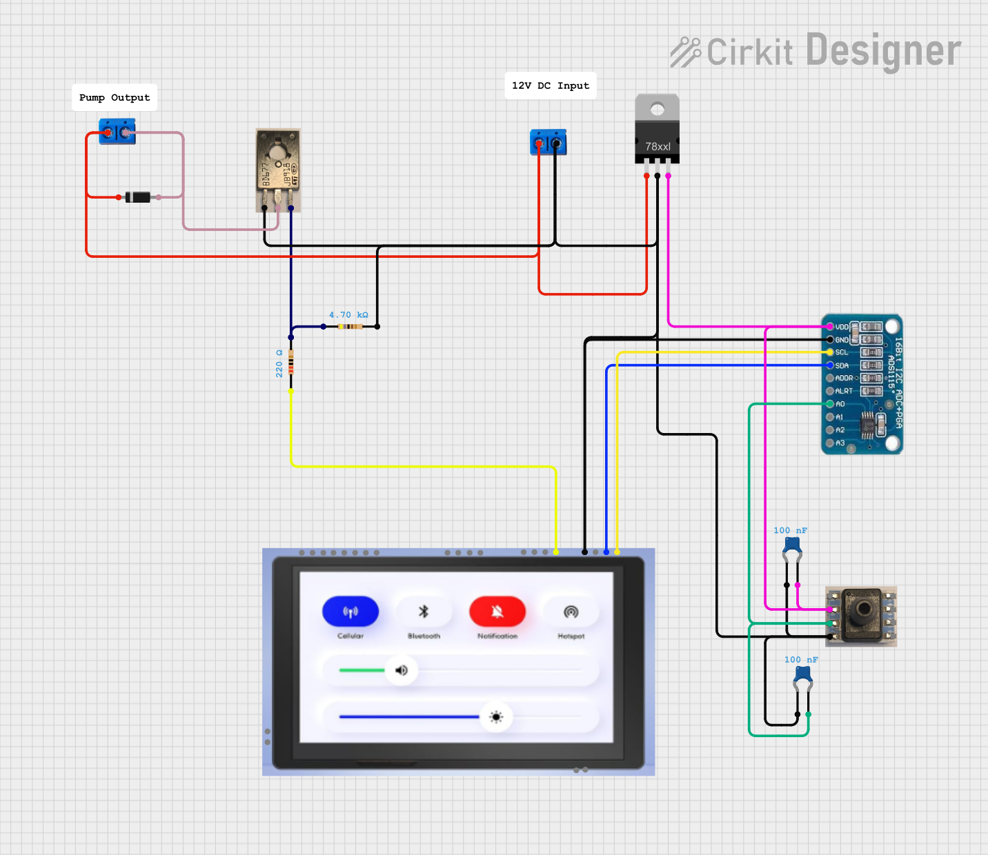
How to Use the Component in a Circuit

  1. Power Supply: Connect the Vcc pin to a +5V power supply and the GND pin to the system ground.
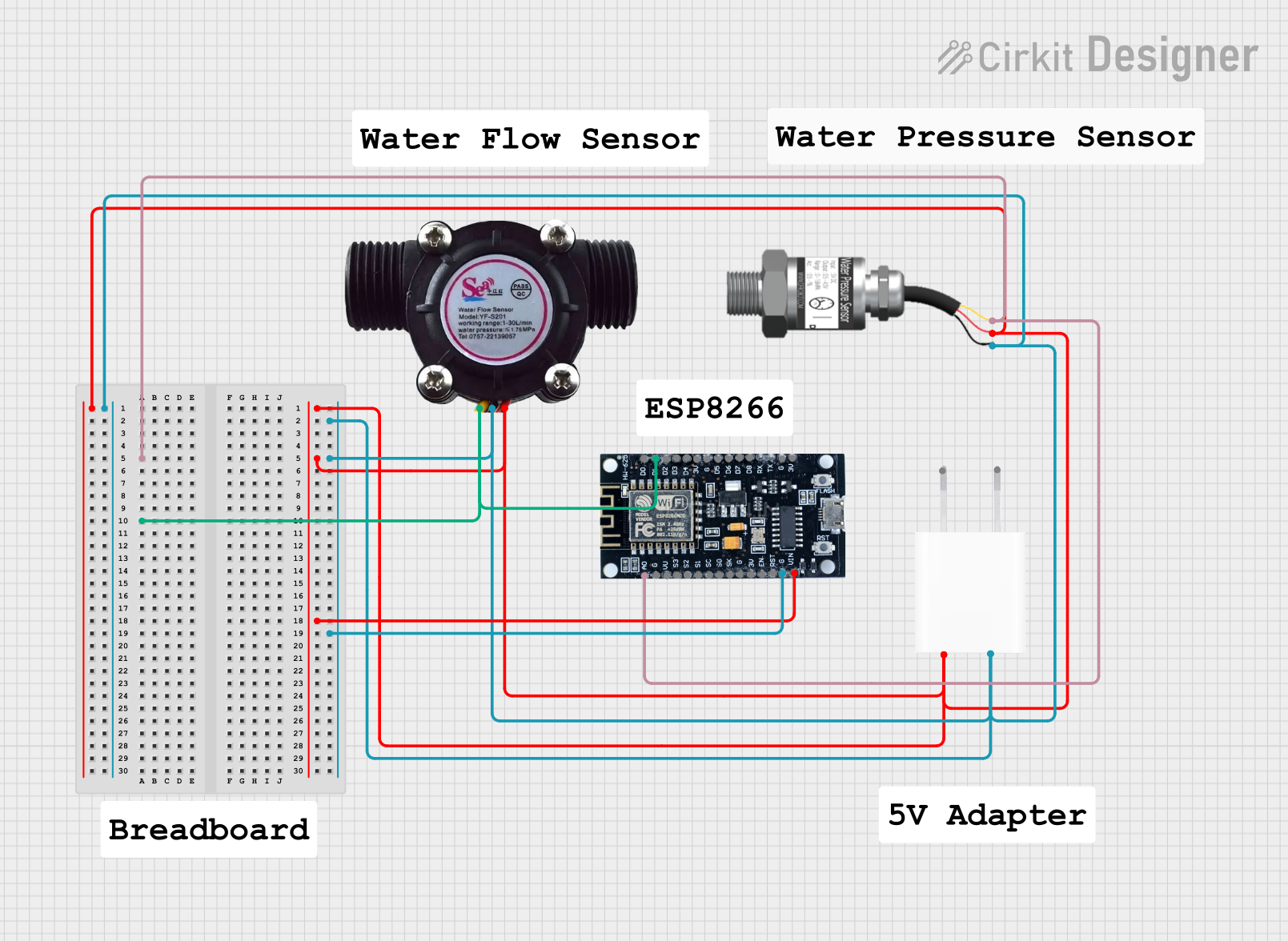
  2. Pressure Inputs: Connect the P1 and P2 pins to the two points in the system where the pressure difference is to be measured.
  3. Output Signal: Connect the Vout pin to an analog input of a microcontroller, such as an Arduino, to read the sensor's output.

Important Considerations and Best Practices

  • Ensure that the pressure inputs do not exceed the sensor's maximum pressure rating.
  • Avoid exposing the sensor to temperatures outside its specified operating range.
  • Use appropriate filtering on the output signal to reduce noise and improve measurement accuracy.
  • Calibrate the sensor if necessary to account for any systematic errors.

Example Code for Arduino UNO

// Define the pin connected to the sensor's output
const int pressureSensorPin = A0;

void setup() {
  // Initialize serial communication at 9600 baud rate
  Serial.begin(9600);
}

void loop() {
  // Read the sensor output (0-1023)
  int sensorValue = analogRead(pressureSensorPin);
  
  // Convert the sensor output to a voltage (0-5V)
  float voltage = sensorValue * (5.0 / 1023.0);
  
  // TODO: Convert the voltage to a pressure difference value
  // This conversion will depend on the specific sensor's characteristics
  
  // Print the pressure difference to the Serial Monitor
  Serial.print("Pressure Difference: ");
  Serial.println(voltage); // Placeholder for actual pressure value
  
  // Wait for a bit before reading the value again
  delay(500);
}

Troubleshooting and FAQs

Common Issues

  • Inaccurate Readings: If the sensor provides inaccurate readings, check for proper calibration and ensure that the pressure inputs are within the specified range.
  • No Output Signal: Verify that the sensor is correctly powered and that all connections are secure. Also, check for any signs of physical damage to the sensor.

Solutions and Tips for Troubleshooting

  • Calibration: Perform a calibration procedure using known pressure values to adjust the sensor's output.
  • Connection Check: Inspect all electrical connections for loose wires or poor contacts.
  • Environmental Factors: Ensure the sensor is not being affected by environmental factors outside its operating range.

FAQs

Q: Can the sensor measure absolute pressure? A: No, differential pressure sensors are designed to measure the pressure difference between two points, not absolute pressure.

Q: What is the typical response time of a differential pressure sensor? A: Response times vary by model, but they are generally fast, often in the millisecond range.

Q: How can I increase the accuracy of my pressure measurements? A: Use signal conditioning, proper calibration, and ensure that the sensor is used within its specified range and environmental conditions.