Cirkit Designer Logo
Cirkit Designer
Your all-in-one circuit design IDE
Home / 
Component Documentation

How to Use Adafruit MLX90393: Examples, Pinouts, and Specs

Image of Adafruit MLX90393
Cirkit Designer LogoDesign with Adafruit MLX90393 in Cirkit Designer

Introduction

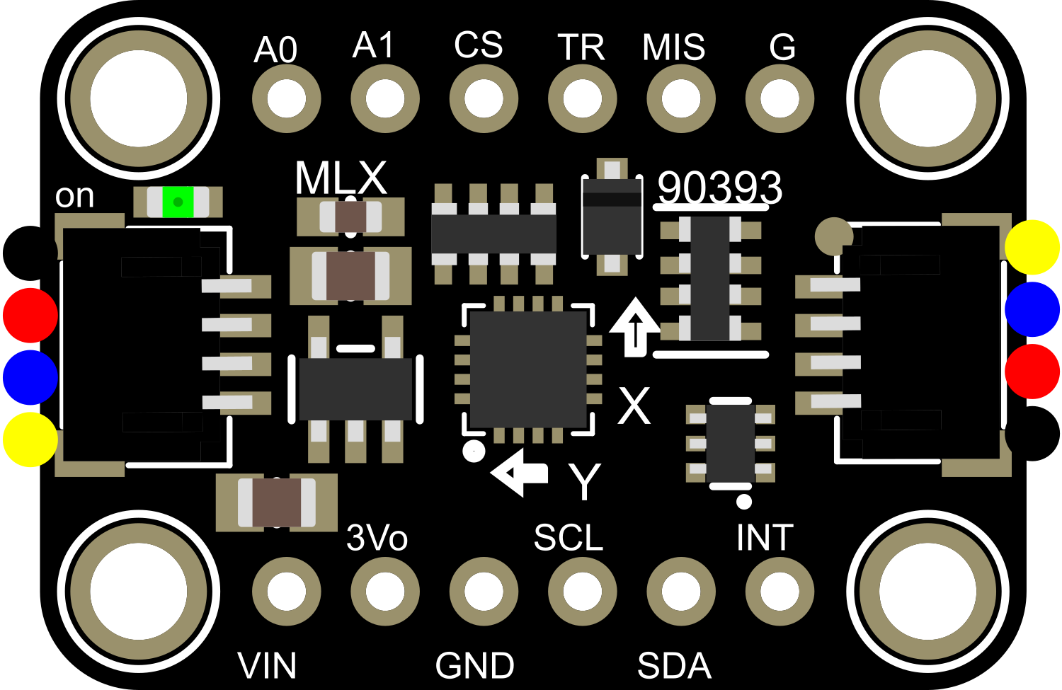
The Adafruit MLX90393 is a versatile and compact magnetic sensor capable of measuring magnetic fields in three dimensions (X, Y, and Z axes). It is based on the MLX90393 sensor from Melexis, which can detect magnetic fields with high accuracy and resolution. This sensor is commonly used in applications such as electronic compasses, position detection, and proximity sensing. Its small form factor and I2C interface make it ideal for embedded systems and IoT devices.

Explore Projects Built with Adafruit MLX90393

Use Cirkit Designer to design, explore, and prototype these projects online. Some projects support real-time simulation. Click "Open Project" to start designing instantly!
Adafruit MPU6050 and VL6180X Sensor Interface with Servo Control
Image of wire: A project utilizing Adafruit MLX90393 in a practical application
This circuit features an Adafruit QT Py microcontroller interfaced with an Adafruit MPU6050 6-axis accelerometer/gyroscope and an Adafruit VL6180X Time of Flight (ToF) distance sensor, both connected via I2C communication. The QT Py also controls a Servomotor SG90, likely for physical actuation based on sensor inputs. The embedded code initializes the sensors, reads their data, and outputs the readings to a serial monitor, with the potential for motion control based on the sensor feedback.
Cirkit Designer LogoOpen Project in Cirkit Designer
Battery-Powered Smart Sensor Hub with Adafruit QT Py RP2040
Image of wearable final: A project utilizing Adafruit MLX90393 in a practical application
This circuit features an Adafruit QT Py RP2040 microcontroller interfaced with an APDS9960 proximity sensor, an MPU6050 accelerometer and gyroscope, and an OLED display via I2C communication. It also includes a buzzer controlled by the microcontroller and is powered by a 3.7V LiPo battery with a toggle switch for power control.
Cirkit Designer LogoOpen Project in Cirkit Designer
Arduino Mega 2560 Multi-Sensor Data Logger with I2C Multiplexer
Image of Gesamt Schaltplan: A project utilizing Adafruit MLX90393 in a practical application
This circuit uses an Arduino Mega 2560 to interface with multiple sensors, including an Adafruit ADXL326 accelerometer, a pressure transducer, and two MLX90614 IR temperature sensors connected via an Adafruit TCA9548A I2C multiplexer. The Arduino reads data from these sensors and outputs the values to the Serial Monitor.
Cirkit Designer LogoOpen Project in Cirkit Designer
Battery-Powered Sensor Hub with Adafruit QT Py RP2040 and OLED Display
Image of 512: A project utilizing Adafruit MLX90393 in a practical application
This circuit features an Adafruit QT Py RP2040 microcontroller interfacing with an MPU-6050 accelerometer, an Adafruit APDS-9960 sensor, and a 0.96" OLED display via I2C communication. It is powered by a 3.7V LiPo battery and includes a green LED with a current-limiting resistor connected to an analog pin of the microcontroller.
Cirkit Designer LogoOpen Project in Cirkit Designer

Explore Projects Built with Adafruit MLX90393

Use Cirkit Designer to design, explore, and prototype these projects online. Some projects support real-time simulation. Click "Open Project" to start designing instantly!
Image of wire: A project utilizing Adafruit MLX90393 in a practical application
Adafruit MPU6050 and VL6180X Sensor Interface with Servo Control
This circuit features an Adafruit QT Py microcontroller interfaced with an Adafruit MPU6050 6-axis accelerometer/gyroscope and an Adafruit VL6180X Time of Flight (ToF) distance sensor, both connected via I2C communication. The QT Py also controls a Servomotor SG90, likely for physical actuation based on sensor inputs. The embedded code initializes the sensors, reads their data, and outputs the readings to a serial monitor, with the potential for motion control based on the sensor feedback.
Cirkit Designer LogoOpen Project in Cirkit Designer
Image of wearable final: A project utilizing Adafruit MLX90393 in a practical application
Battery-Powered Smart Sensor Hub with Adafruit QT Py RP2040
This circuit features an Adafruit QT Py RP2040 microcontroller interfaced with an APDS9960 proximity sensor, an MPU6050 accelerometer and gyroscope, and an OLED display via I2C communication. It also includes a buzzer controlled by the microcontroller and is powered by a 3.7V LiPo battery with a toggle switch for power control.
Cirkit Designer LogoOpen Project in Cirkit Designer
Image of Gesamt Schaltplan: A project utilizing Adafruit MLX90393 in a practical application
Arduino Mega 2560 Multi-Sensor Data Logger with I2C Multiplexer
This circuit uses an Arduino Mega 2560 to interface with multiple sensors, including an Adafruit ADXL326 accelerometer, a pressure transducer, and two MLX90614 IR temperature sensors connected via an Adafruit TCA9548A I2C multiplexer. The Arduino reads data from these sensors and outputs the values to the Serial Monitor.
Cirkit Designer LogoOpen Project in Cirkit Designer
Image of 512: A project utilizing Adafruit MLX90393 in a practical application
Battery-Powered Sensor Hub with Adafruit QT Py RP2040 and OLED Display
This circuit features an Adafruit QT Py RP2040 microcontroller interfacing with an MPU-6050 accelerometer, an Adafruit APDS-9960 sensor, and a 0.96" OLED display via I2C communication. It is powered by a 3.7V LiPo battery and includes a green LED with a current-limiting resistor connected to an analog pin of the microcontroller.
Cirkit Designer LogoOpen Project in Cirkit Designer

Technical Specifications

Key Features

  • Magnetic field sensing in 3D: X, Y, and Z
  • Operating Voltage: 2.2V to 3.6V
  • Current Consumption: 100 μA (typical)
  • Resolution: up to 0.161 μT per LSB
  • Communication Interface: I2C (up to 1 MHz)
  • Operating Temperature Range: -20°C to 85°C

Pin Configuration and Descriptions

Pin Number Name Description
1 VIN Supply voltage (2.2V to 3.6V)
2 GND Ground connection
3 SDA I2C Data Line
4 SCL I2C Clock Line
5 INT Interrupt output (active low)
6 DRDY Data Ready output (active low)

Usage Instructions

Integration with a Circuit

To use the Adafruit MLX90393 with a microcontroller like an Arduino UNO, follow these steps:

  1. Connect the VIN pin to the 3.3V output on the Arduino.
  2. Connect the GND pin to one of the ground pins on the Arduino.
  3. Connect the SDA pin to the A4 pin (SDA) on the Arduino.
  4. Connect the SCL pin to the A5 pin (SCL) on the Arduino.
  5. (Optional) Connect the INT pin to an available digital pin if interrupt functionality is required.
  6. (Optional) Connect the DRDY pin to another available digital pin if data ready indication is needed.

Best Practices

  • Ensure that the power supply is stable and within the specified voltage range.
  • Use pull-up resistors on the I2C lines if they are not already present on the microcontroller board.
  • Avoid placing the sensor near strong magnetic fields that may exceed its maximum specifications.
  • When mounting the sensor, ensure that it is firmly secured and that there is minimal mechanical stress on the pins.

Example Code for Arduino UNO

#include <Wire.h>
#include <Adafruit_MLX90393.h>

// Create an MLX90393 instance
Adafruit_MLX90393 mlx = Adafruit_MLX90393();

void setup() {
  Serial.begin(9600);
  // Initialize the sensor
  if (!mlx.begin()) {
    Serial.println("Failed to initialize MLX90393!");
    while (1);
  }
  Serial.println("MLX90393 initialized.");
}

void loop() {
  // Read magnetic field data
  float x, y, z;
  mlx.readData(&x, &y, &z);
  // Print the results
  Serial.print("X: "); Serial.print(x); Serial.print(" uT, ");
  Serial.print("Y: "); Serial.print(y); Serial.print(" uT, ");
  Serial.print("Z: "); Serial.print(z); Serial.println(" uT");
  // Small delay before the next reading
  delay(500);
}

Troubleshooting and FAQs

Common Issues

  • Sensor not responding: Ensure that the wiring is correct and that the sensor is properly powered.
  • Inaccurate readings: Calibrate the sensor if possible, and make sure it is not affected by nearby magnetic sources.
  • No data on I2C: Check for proper pull-up resistors and that the I2C address is correct.

FAQs

Q: Can the MLX90393 be used with a 5V microcontroller? A: Yes, but ensure that the sensor's VIN pin is connected to a 3.3V supply, and use logic level converters for SDA and SCL lines if necessary.

Q: How can I change the I2C address of the sensor? A: The I2C address is fixed for the MLX90393. If you need to use multiple sensors on the same bus, you will need an I2C multiplexer.

Q: What is the maximum range of magnetic field the MLX90393 can measure? A: The MLX90393 can measure magnetic fields up to ±5 mT.

Q: How do I use the interrupt and data ready pins? A: The INT and DRDY pins can be connected to digital pins on your microcontroller and configured to trigger an interrupt when a measurement is ready or when certain thresholds are exceeded.

For further assistance, consult the Adafruit MLX90393 datasheet and the library's documentation.