Cirkit Designer Logo
Cirkit Designer
Your all-in-one circuit design IDE
Home / 
Component Documentation

How to Use GEMMA v2: Examples, Pinouts, and Specs

Image of GEMMA v2
Cirkit Designer LogoDesign with GEMMA v2 in Cirkit Designer

Introduction

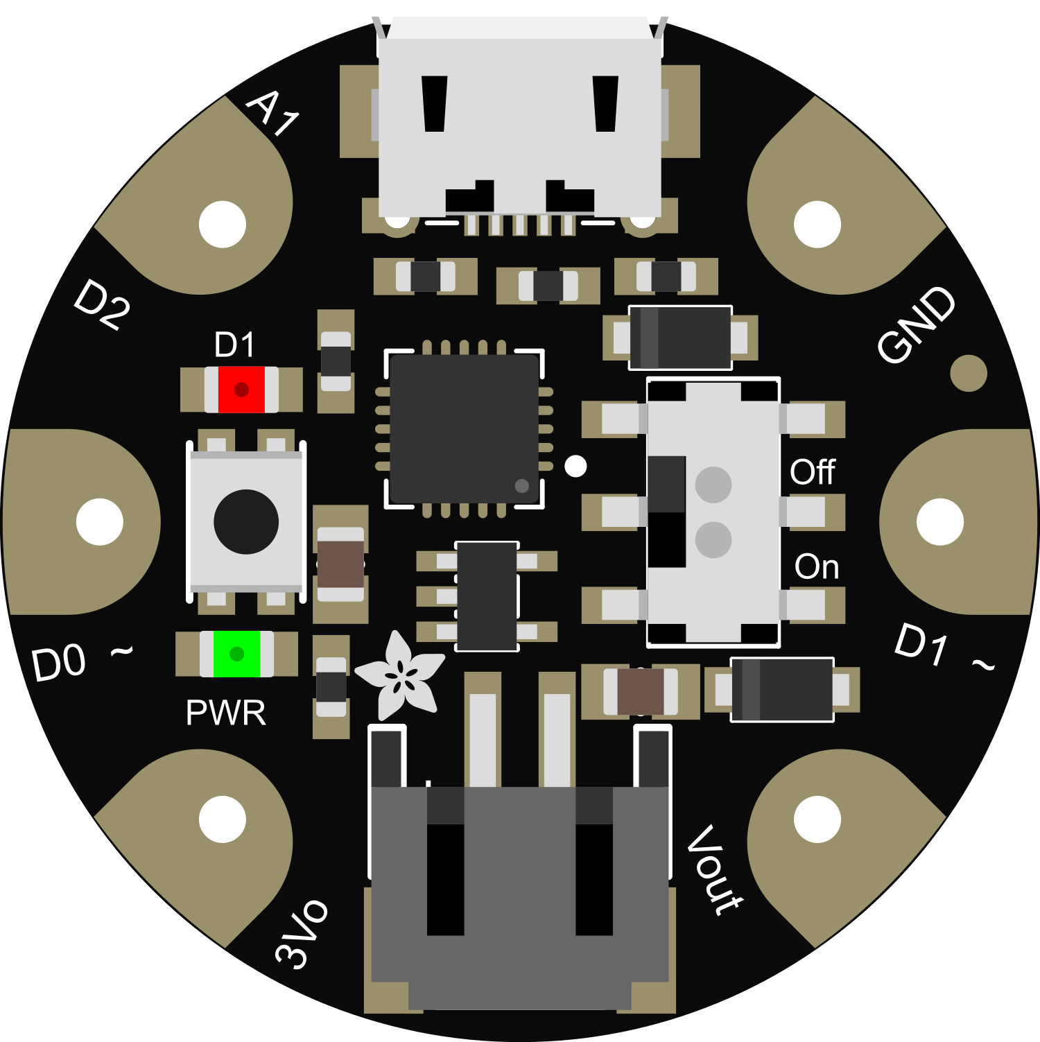
The GEMMA v2 is a tiny microcontroller board designed specifically for wearable electronics projects. It is built around the ATtiny85 microcontroller, which is a versatile and low-power chip ideal for small-scale projects. The GEMMA v2 is perfect for adding interactive elements to clothing, accessories, and other fabric-based projects due to its small size and ease of use.

Explore Projects Built with GEMMA v2

Use Cirkit Designer to design, explore, and prototype these projects online. Some projects support real-time simulation. Click "Open Project" to start designing instantly!
ESP32-Based Voice Assistant with Battery-Powered Microphone and Speaker
Image of Minor: A project utilizing GEMMA v2 in a practical application
This circuit is a voice-controlled system that uses an ESP32 microcontroller to process audio input from a microphone, send the data to a Gemini API for speech-to-text conversion, and output responses through a speaker. It includes an IR sensor for additional input, an LED for status indication, and a battery with a charging module for power management.
Cirkit Designer LogoOpen Project in Cirkit Designer
Arduino Mega 2560 Based Security System with Fingerprint Authentication and SMS Alerts
Image of Door security system: A project utilizing GEMMA v2 in a practical application
This circuit features an Arduino Mega 2560 microcontroller interfaced with a SIM800L GSM module, two fingerprint scanners, an I2C LCD display, an IR sensor, and a piezo buzzer. Power management is handled by a PowerBoost 1000 Basic Pad USB, a TP4056 charging module, and a Li-ion 18650 battery, with an option to use a Mini AC-DC 110V-230V to 5V 700mA module for direct power supply. The primary functionality appears to be a security system with GSM communication capabilities, biometric access control, and visual/audible feedback.
Cirkit Designer LogoOpen Project in Cirkit Designer
Arduino Mega 2560 Biometric Security System with Wi-Fi Connectivity
Image of Health Monitoring Device (Collab): A project utilizing GEMMA v2 in a practical application
This is a multi-functional sensor system controlled by an Arduino Mega 2560, designed to read biometric data from a pulse oximeter and an infrared thermometer, authenticate using a fingerprint scanner, display information on an OLED screen, and transmit data wirelessly via an ESP8266 module. User inputs can be received through two pushbuttons, and the system's power distribution is managed through common ground and voltage supply nets.
Cirkit Designer LogoOpen Project in Cirkit Designer
I2C-Controlled OLED Display with External EEPROM and Interactive Pushbuttons
Image of godmode: A project utilizing GEMMA v2 in a practical application
This is a microcontroller-based interactive device featuring a Wemos D1 Mini, an OLED display, external EEPROM, and an I/O expander. It includes user input buttons and status LEDs, with potential MIDI interface capabilities.
Cirkit Designer LogoOpen Project in Cirkit Designer

Explore Projects Built with GEMMA v2

Use Cirkit Designer to design, explore, and prototype these projects online. Some projects support real-time simulation. Click "Open Project" to start designing instantly!
Image of Minor: A project utilizing GEMMA v2 in a practical application
ESP32-Based Voice Assistant with Battery-Powered Microphone and Speaker
This circuit is a voice-controlled system that uses an ESP32 microcontroller to process audio input from a microphone, send the data to a Gemini API for speech-to-text conversion, and output responses through a speaker. It includes an IR sensor for additional input, an LED for status indication, and a battery with a charging module for power management.
Cirkit Designer LogoOpen Project in Cirkit Designer
Image of Door security system: A project utilizing GEMMA v2 in a practical application
Arduino Mega 2560 Based Security System with Fingerprint Authentication and SMS Alerts
This circuit features an Arduino Mega 2560 microcontroller interfaced with a SIM800L GSM module, two fingerprint scanners, an I2C LCD display, an IR sensor, and a piezo buzzer. Power management is handled by a PowerBoost 1000 Basic Pad USB, a TP4056 charging module, and a Li-ion 18650 battery, with an option to use a Mini AC-DC 110V-230V to 5V 700mA module for direct power supply. The primary functionality appears to be a security system with GSM communication capabilities, biometric access control, and visual/audible feedback.
Cirkit Designer LogoOpen Project in Cirkit Designer
Image of Health Monitoring Device (Collab): A project utilizing GEMMA v2 in a practical application
Arduino Mega 2560 Biometric Security System with Wi-Fi Connectivity
This is a multi-functional sensor system controlled by an Arduino Mega 2560, designed to read biometric data from a pulse oximeter and an infrared thermometer, authenticate using a fingerprint scanner, display information on an OLED screen, and transmit data wirelessly via an ESP8266 module. User inputs can be received through two pushbuttons, and the system's power distribution is managed through common ground and voltage supply nets.
Cirkit Designer LogoOpen Project in Cirkit Designer
Image of godmode: A project utilizing GEMMA v2 in a practical application
I2C-Controlled OLED Display with External EEPROM and Interactive Pushbuttons
This is a microcontroller-based interactive device featuring a Wemos D1 Mini, an OLED display, external EEPROM, and an I/O expander. It includes user input buttons and status LEDs, with potential MIDI interface capabilities.
Cirkit Designer LogoOpen Project in Cirkit Designer

Common Applications and Use Cases

  • Wearable technology (e.g., smart clothing, fitness trackers)
  • Interactive costumes
  • Soft robotics
  • Educational projects and DIY crafts
  • Prototyping IoT devices

Technical Specifications

Key Technical Details

  • Microcontroller: ATtiny85
  • Operating Voltage: 3.3V
  • Input Voltage: 4-16V (via battery port)
  • Digital I/O Pins: 3 (of which 2 are PWM capable)
  • Analog Input Pins: 1 (shared with digital I/O)
  • Flash Memory: 8 KB (ATtiny85) of which 2.75 KB used by bootloader
  • SRAM: 512 bytes
  • EEPROM: 512 bytes
  • Clock Speed: 8 MHz
  • Diameter: 27mm
  • Height: 7mm
  • Weight: 1.87 grams

Pin Configuration and Descriptions

Pin Number Name Description
1 Vout 3.3V output from the onboard regulator
2 A1/D2 Analog input 1 or Digital I/O pin 2
3 A2/D0 Analog input 2 or Digital I/O pin 0, also PWM capable
4 A3/D1 Analog input 3 or Digital I/O pin 1, also PWM capable
5 GND Ground
6 BAT Battery input for an external power source
7 3Vo 3.3V output, can be used to power external sensors or components
8 USB Micro USB connection for programming and power

Usage Instructions

How to Use the GEMMA v2 in a Circuit

  1. Powering the GEMMA v2: Connect a battery to the BAT pin or power the GEMMA v2 through the USB port.
  2. Programming: Use the micro USB port to connect the GEMMA v2 to your computer. You will need to install the Adafruit AVR boards package in the Arduino IDE to program the ATtiny85.
  3. Connecting Components: Attach sensors, LEDs, or other components to the I/O pins. Ensure that the components are compatible with the 3.3V logic level.
  4. Grounding: Connect the GND pin to the ground of your circuit to complete the circuit.

Important Considerations and Best Practices

  • Always check the power requirements of external components to prevent damage.
  • When sewing with conductive thread, ensure there are no short circuits.
  • Use a multimeter to verify connections and voltages.
  • Avoid placing the GEMMA v2 on conductive surfaces to prevent shorts.

Example Code for Arduino UNO

// Blink example for GEMMA v2

void setup() {
  // Initialize digital pin D1 as an output.
  pinMode(1, OUTPUT);
}

void loop() {
  digitalWrite(1, HIGH);   // Turn on the LED
  delay(1000);             // Wait for a second
  digitalWrite(1, LOW);    // Turn off the LED
  delay(1000);             // Wait for a second
}

Troubleshooting and FAQs

Common Issues

  • GEMMA v2 not recognized by computer: Ensure the micro USB cable is data-capable and the GEMMA v2 drivers are installed.
  • LEDs or sensors not working: Verify that the components are correctly connected and compatible with 3.3V logic.
  • Program not running: Check that the correct board and port are selected in the Arduino IDE.

Solutions and Tips for Troubleshooting

  • If the GEMMA v2 is not detected, try a different USB cable or port.
  • Use a multimeter to check for continuity and correct voltages.
  • Ensure that the battery used is within the specified voltage range.

FAQs

Q: Can I power the GEMMA v2 with a 5V supply? A: No, the recommended input voltage is 4-16V via the battery port. The onboard regulator will bring it down to 3.3V.

Q: How do I sew the GEMMA v2 onto fabric? A: Use conductive thread to sew through the large pads around the edge of the board. Make sure to knot and seal the ends to prevent fraying.

Q: Is the GEMMA v2 washable? A: The GEMMA v2 is not waterproof. Remove it from your project before washing.

For further assistance, consult the Adafruit forums or the extensive online community resources dedicated to GEMMA and wearable electronics.