How to Use lora ra-02: Examples, Pinouts, and Specs
Introduction
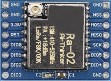
The LoRa RA-02, manufactured by Ai Thinker, is a low-power, long-range transceiver module that utilizes LoRa (Long Range) modulation technology. This module is specifically designed for wireless communication in IoT applications, offering exceptional range and low power consumption. With its ability to operate over several kilometers in open areas, the RA-02 is ideal for applications requiring low data rates and reliable communication over long distances.
Explore Projects Built with lora ra-02
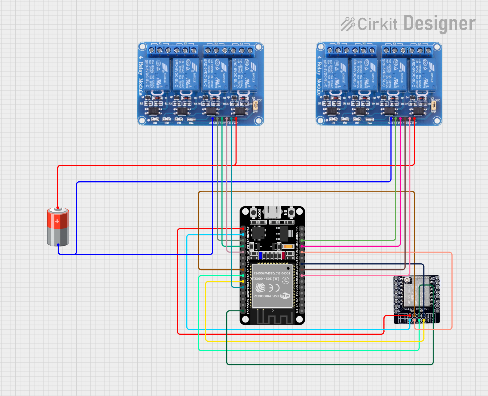

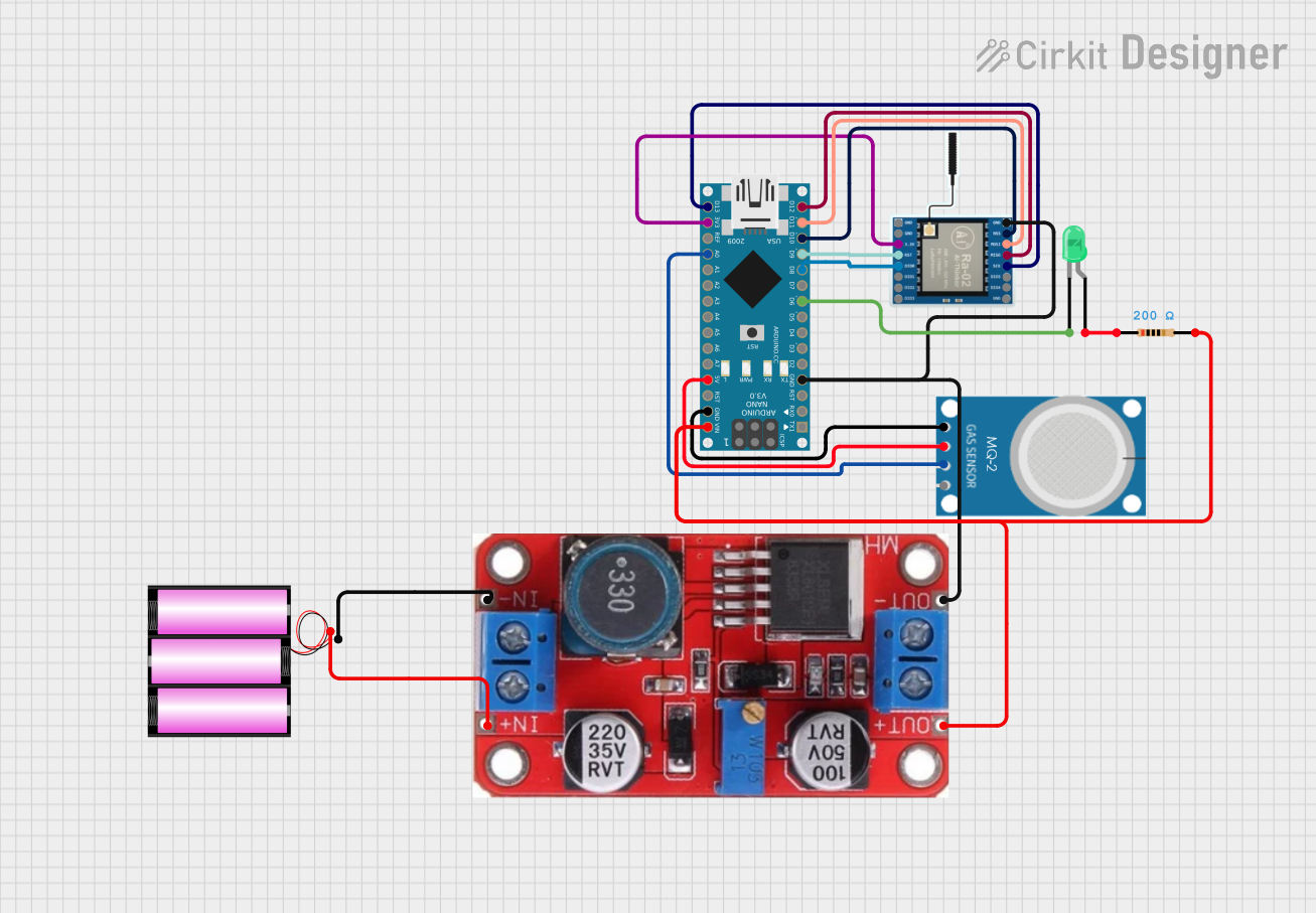
Explore Projects Built with lora ra-02
Common Applications
- Remote Sensing: Environmental monitoring, weather stations, and industrial sensors.
- Smart Agriculture: Soil moisture monitoring, livestock tracking, and irrigation systems.
- Smart Cities: Parking sensors, streetlight control, and waste management.
- Home Automation: Wireless control of devices and security systems.
- Asset Tracking: GPS-free tracking of goods and vehicles.
Technical Specifications
The LoRa RA-02 module is built around the Semtech SX1278 chip, which supports LoRa modulation for robust and long-range communication. Below are the key technical details:
Key Specifications
| Parameter | Value |
|---|---|
| Operating Voltage | 1.8V to 3.7V |
| Operating Current | 10.8mA (transmit), 10.3mA (receive) |
| Sleep Current | < 200nA |
| Frequency Range | 433 MHz (default) |
| Modulation | LoRa, FSK |
| Data Rate | 0.018 kbps to 37.5 kbps |
| Output Power | Up to +20 dBm |
| Sensitivity | -148 dBm |
| Communication Range | Up to 10 km (line of sight) |
| Interface | SPI |
| Dimensions | 16 x 16 mm |
Pin Configuration
The RA-02 module has 16 pins, as detailed in the table below:
| Pin Number | Pin Name | Description |
|---|---|---|
| 1 | GND | Ground |
| 2 | DIO1 | Digital I/O Pin 1 |
| 3 | DIO2 | Digital I/O Pin 2 |
| 4 | DIO3 | Digital I/O Pin 3 |
| 5 | DIO4 | Digital I/O Pin 4 |
| 6 | DIO5 | Digital I/O Pin 5 |
| 7 | GND | Ground |
| 8 | ANT | Antenna Connection |
| 9 | VCC | Power Supply (1.8V to 3.7V) |
| 10 | RESET | Reset Pin |
| 11 | NSS | SPI Chip Select |
| 12 | SCK | SPI Clock |
| 13 | MOSI | SPI Master Out Slave In |
| 14 | MISO | SPI Master In Slave Out |
| 15 | DIO0 | Digital I/O Pin 0 |
| 16 | GND | Ground |
Usage Instructions
How to Use the LoRa RA-02 in a Circuit
- Power Supply: Connect the VCC pin to a regulated power source (1.8V to 3.7V). Ensure the GND pins are connected to the ground of your circuit.
- SPI Interface: Connect the SPI pins (NSS, SCK, MOSI, MISO) to the corresponding SPI pins of your microcontroller.
- Antenna: Attach a 433 MHz antenna to the ANT pin for optimal performance.
- Reset: Use the RESET pin to initialize the module when required.
- Digital I/O Pins: Use the DIO pins for interrupt handling or additional control signals.
Important Considerations
- Antenna Placement: Ensure the antenna is placed away from other components to avoid interference.
- Power Supply: Use a stable power source to prevent communication issues.
- Frequency Compliance: Verify that the operating frequency (433 MHz) complies with local regulations.
- Heat Dissipation: Avoid overheating by ensuring proper ventilation around the module.
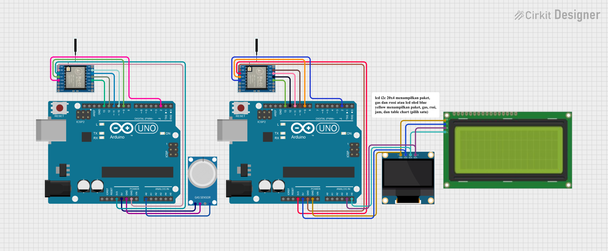
Example: Connecting LoRa RA-02 to Arduino UNO
Below is an example of how to connect the LoRa RA-02 module to an Arduino UNO and send a simple message.
Wiring Diagram
| LoRa RA-02 Pin | Arduino UNO Pin |
|---|---|
| VCC | 3.3V |
| GND | GND |
| NSS | D10 |
| SCK | D13 |
| MOSI | D11 |
| MISO | D12 |
| RESET | D9 |
| DIO0 | D2 |
Arduino Code Example
#include <SPI.h>
#include <LoRa.h> // Include the LoRa library

#define NSS 10    // LoRa NSS pin connected to Arduino pin 10
#define RESET 9   // LoRa RESET pin connected to Arduino pin 9
#define DIO0 2    // LoRa DIO0 pin connected to Arduino pin 2

void setup() {
  Serial.begin(9600); // Initialize serial communication
  while (!Serial);

  Serial.println("Initializing LoRa module...");

  // Initialize LoRa module with NSS, RESET, and DIO0 pins
  if (!LoRa.begin(433E6)) { // Set frequency to 433 MHz
    Serial.println("LoRa initialization failed!");
    while (1);
  }

  Serial.println("LoRa initialized successfully!");
}

void loop() {
  Serial.println("Sending message...");
  LoRa.beginPacket(); // Start a new LoRa packet
  LoRa.print("Hello, LoRa!"); // Add message to the packet
  LoRa.endPacket(); // Send the packet

  delay(5000); // Wait 5 seconds before sending the next message
}
Notes
- Install the LoRa library in the Arduino IDE before uploading the code. You can find it in the Library Manager.
- Ensure the module is powered by 3.3V, as higher voltages may damage it.
Troubleshooting and FAQs
Common Issues
No Communication Between Modules
- Cause: Incorrect wiring or mismatched frequency settings.
- Solution: Double-check the wiring and ensure both modules are set to the same frequency (e.g., 433 MHz).
Short Communication Range
- Cause: Poor antenna placement or interference.
- Solution: Use a high-quality antenna and place it away from other electronic components.
Module Not Initializing
- Cause: Incorrect power supply or SPI connection.
- Solution: Verify the power supply voltage (1.8V to 3.7V) and ensure proper SPI connections.
High Power Consumption
- Cause: Module not entering sleep mode.
- Solution: Use the appropriate commands to put the module into sleep mode when not in use.
FAQs
Q: Can the RA-02 module operate at 868 MHz or 915 MHz?
- A: No, the RA-02 is designed for 433 MHz operation. For other frequencies, consider using a different LoRa module.
Q: What is the maximum data rate supported by the RA-02?
- A: The maximum data rate is 37.5 kbps, depending on the configuration.
Q: Can I use the RA-02 module with a 5V microcontroller?
- A: Yes, but you must use a level shifter to convert the 5V logic to 3.3V for the module.
Q: How can I increase the communication range?
- A: Use a high-gain antenna, ensure line-of-sight communication, and reduce the data rate.
This concludes the documentation for the LoRa RA-02 module.