How to Use lcd 20*4: Examples, Pinouts, and Specs
Introduction
The LCD 20x4 is a versatile display module capable of showing 20 characters per line across 4 lines. Manufactured by A (Part ID: A), this Liquid Crystal Display is widely used in embedded systems for presenting text and simple graphics. It supports both parallel and serial interfaces, making it compatible with a variety of microcontrollers and development boards.
Explore Projects Built with lcd 20*4

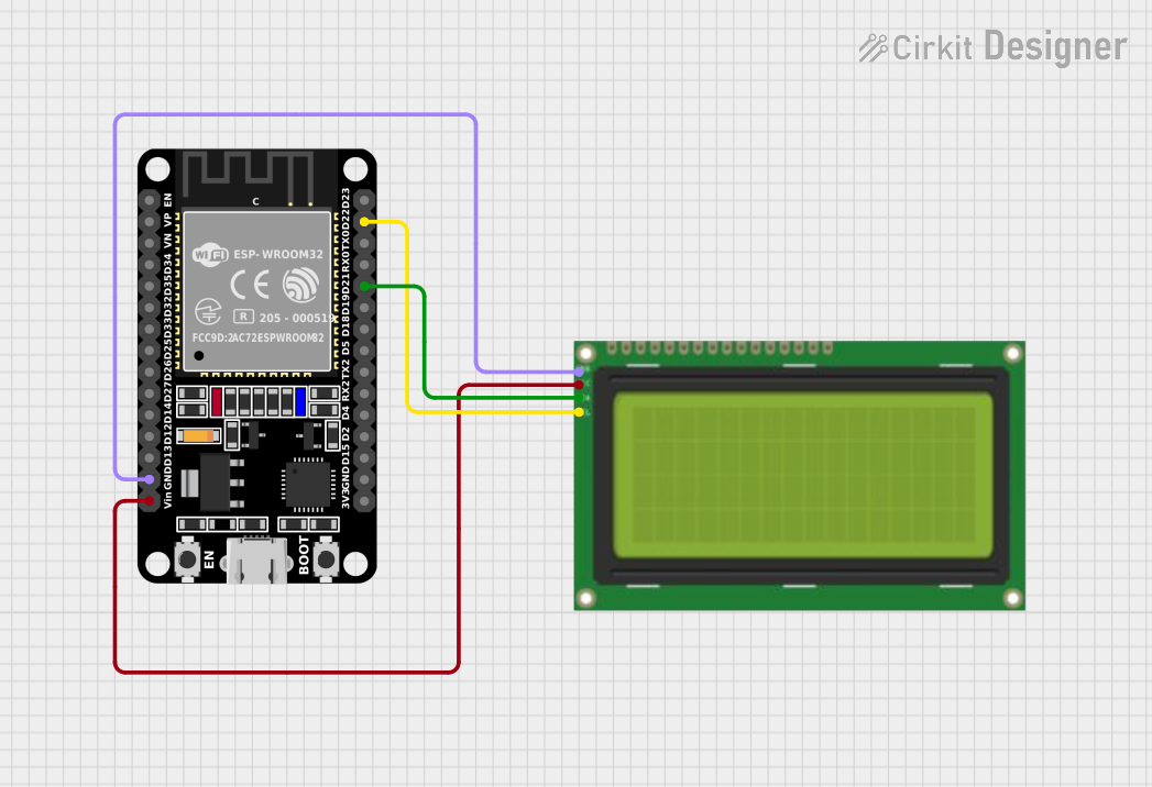
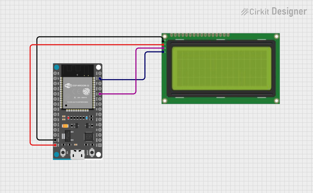
Explore Projects Built with lcd 20*4
Common Applications
- Embedded Systems: Displaying sensor data, system status, or user interfaces.
- DIY Projects: Used in hobbyist projects for text-based outputs.
- Industrial Equipment: Displaying machine parameters or diagnostics.
- Home Automation: Showing temperature, humidity, or other environmental data.
Technical Specifications
Key Technical Details
| Parameter | Value |
|---|---|
| Display Type | LCD (Liquid Crystal Display) |
| Manufacturer | A |
| Manufacturer Part ID | A |
| Display Size | 20 characters x 4 lines |
| Operating Voltage | 4.7V - 5.3V |
| Interface Type | Parallel (4-bit/8-bit) or Serial (I2C/SPI) |
| Backlight | LED (adjustable brightness) |
| Character Size | 5x8 dot matrix per character |
| Operating Temperature | -20°C to +70°C |
| Dimensions | ~98mm x 60mm x 12mm |
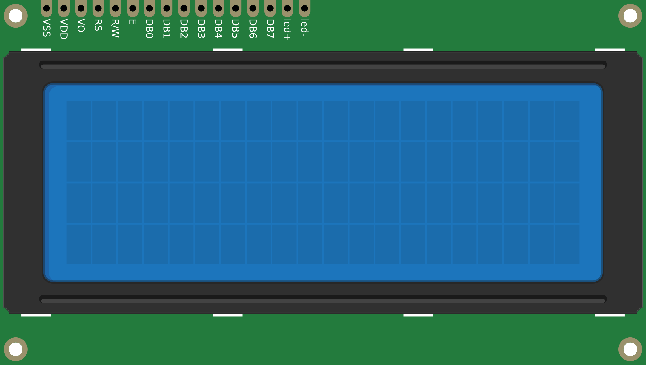
Pin Configuration and Descriptions
Parallel Interface (16 Pins)
| Pin No. | Name | Description |
|---|---|---|
| 1 | VSS | Ground (0V) |
| 2 | VDD | Power supply (4.7V - 5.3V) |
| 3 | VO | Contrast adjustment (connect to a potentiometer for contrast control) |
| 4 | RS | Register Select (0: Command, 1: Data) |
| 5 | RW | Read/Write (0: Write, 1: Read) |
| 6 | E | Enable signal (triggers data read/write) |
| 7-14 | D0-D7 | Data pins (D0-D3 optional in 4-bit mode; D0-D7 used in 8-bit mode) |
| 15 | A | Backlight anode (connect to +5V via a resistor for brightness control) |
| 16 | K | Backlight cathode (connect to ground) |
I2C Interface (with I2C Adapter)
| Pin No. | Name | Description |
|---|---|---|
| 1 | GND | Ground (0V) |
| 2 | VCC | Power supply (4.7V - 5.3V) |
| 3 | SDA | Serial Data Line (I2C data) |
| 4 | SCL | Serial Clock Line (I2C clock) |
Usage Instructions
Using the LCD 20x4 in a Circuit
- Power Supply: Connect the VDD pin to a 5V power source and the VSS pin to ground.
- Contrast Adjustment: Connect the VO pin to the wiper of a 10kΩ potentiometer. Connect one end of the potentiometer to 5V and the other to ground. Adjust the potentiometer to set the display contrast.
- Interface Selection:
- For parallel mode, connect the data pins (D0-D7 or D4-D7 for 4-bit mode) and control pins (RS, RW, E) to the microcontroller.
- For I2C mode, use an I2C adapter and connect the SDA and SCL pins to the microcontroller's I2C pins.
- Backlight: Connect the A pin to 5V (via a current-limiting resistor, e.g., 220Ω) and the K pin to ground.
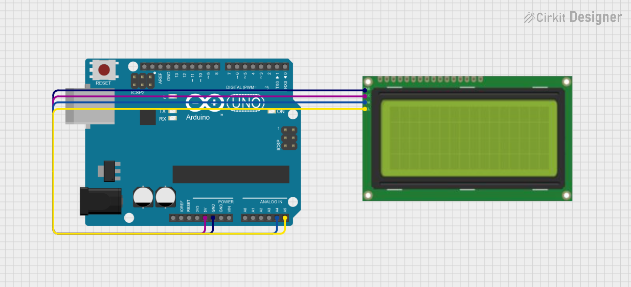
Example: Connecting to Arduino UNO (I2C Mode)
To use the LCD 20x4 with an Arduino UNO via I2C, follow these steps:
- Connect the GND and VCC pins of the I2C adapter to the Arduino's GND and 5V pins, respectively.
- Connect the SDA pin to Arduino's A4 pin and the SCL pin to Arduino's A5 pin.
- Install the
LiquidCrystal_I2Clibrary in the Arduino IDE. - Use the following example code to display text:
#include <Wire.h>
#include <LiquidCrystal_I2C.h>

// Initialize the LCD with I2C address 0x27 and dimensions 20x4
LiquidCrystal_I2C lcd(0x27, 20, 4);

void setup() {
  lcd.init(); // Initialize the LCD
  lcd.backlight(); // Turn on the backlight

  // Display text on the LCD
  lcd.setCursor(0, 0); // Set cursor to column 0, row 0
  lcd.print("Hello, World!"); // Print text on the first line
  lcd.setCursor(0, 1); // Set cursor to column 0, row 1
  lcd.print("LCD 20x4 Display"); // Print text on the second line
}

void loop() {
  // No actions in the loop
}
Important Considerations
- Power Supply: Ensure a stable 5V power source to avoid flickering or malfunction.
- Contrast Adjustment: Improper contrast settings may result in a blank or unreadable display.
- I2C Address: The default I2C address is typically
0x27, but it may vary. Use an I2C scanner sketch to confirm the address if needed.
Troubleshooting and FAQs
Common Issues and Solutions
- Blank Screen:
- Check the power connections and ensure the LCD is receiving 5V.
- Adjust the contrast using the potentiometer connected to the VO pin.
- Flickering Display:
- Verify that the power supply is stable and capable of providing sufficient current.
- Ensure proper grounding of all components.
- Incorrect Characters or No Response:
- Double-check the wiring, especially the data and control pins.
- Ensure the correct interface mode (parallel or I2C) is selected in the code.
- I2C Not Working:
- Confirm the I2C address using an I2C scanner sketch.
- Check the SDA and SCL connections for continuity.
FAQs
Q: Can I use the LCD 20x4 with a 3.3V microcontroller?
A: The LCD requires a 5V power supply. Use a level shifter for 3.3V microcontrollers.Q: How do I dim the backlight?
A: Use a higher-value resistor (e.g., 470Ω) in series with the backlight anode pin.Q: Can I display custom characters?
A: Yes, the LCD supports custom characters. Refer to thecreateChar()function in theLiquidCrystallibrary.
This concludes the documentation for the LCD 20x4 module.