How to Use DM13A: Examples, Pinouts, and Specs
Introduction
The DM13A is a versatile 16-channel constant current LED driver designed to control multiple LEDs in electronic displays and lighting applications. It ensures consistent brightness across all LEDs by providing a constant current, regardless of variations in supply voltage or LED forward voltage. This makes it an ideal choice for applications such as LED matrices, signage, and decorative lighting.
Explore Projects Built with DM13A


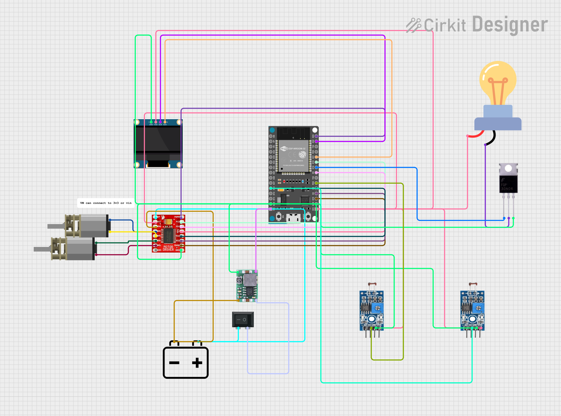

Explore Projects Built with DM13A
Technical Specifications
Key Technical Details
| Parameter | Value |
|---|---|
| Supply Voltage | 3.3V to 5.5V |
| Output Current | 5mA to 60mA (programmable) |
| Output Channels | 16 |
| Data Transfer Rate | Up to 25 MHz |
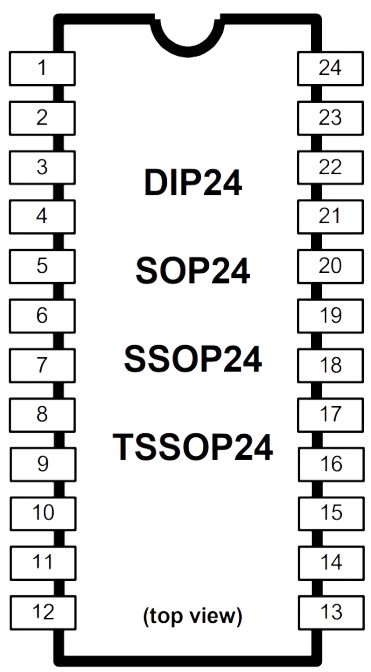
| Package | SOP-24, SSOP-24 |
| Operating Temperature | -40°C to +85°C |
Pin Configuration and Descriptions
| Pin No. | Pin Name | Description |
|---|---|---|
| 1 | GND | Ground |
| 2 | SDI | Serial Data Input |
| 3 | CLK | Clock Input |
| 4 | LE | Latch Enable |
| 5 | OUT0 | Output Channel 0 |
| 6 | OUT1 | Output Channel 1 |
| 7 | OUT2 | Output Channel 2 |
| 8 | OUT3 | Output Channel 3 |
| 9 | OUT4 | Output Channel 4 |
| 10 | OUT5 | Output Channel 5 |
| 11 | OUT6 | Output Channel 6 |
| 12 | OUT7 | Output Channel 7 |
| 13 | OUT8 | Output Channel 8 |
| 14 | OUT9 | Output Channel 9 |
| 15 | OUT10 | Output Channel 10 |
| 16 | OUT11 | Output Channel 11 |
| 17 | OUT12 | Output Channel 12 |
| 18 | OUT13 | Output Channel 13 |
| 19 | OUT14 | Output Channel 14 |
| 20 | OUT15 | Output Channel 15 |
| 21 | VDD | Supply Voltage |
| 22 | R-EXT | External Resistor for Current Setting |
| 23 | SDO | Serial Data Output |
| 24 | OE | Output Enable |
Usage Instructions
How to Use the DM13A in a Circuit
- Power Supply: Connect the VDD pin to a 3.3V to 5.5V power supply and the GND pin to ground.
- Current Setting: Connect an external resistor between the R-EXT pin and ground to set the desired output current. The value of the resistor determines the current through each LED.
- Data Input: Connect the SDI pin to the microcontroller's data output pin. The CLK pin should be connected to the microcontroller's clock output pin.
- Latch Enable: Connect the LE pin to a microcontroller pin to latch the data into the output registers.
- Output Enable: Connect the OE pin to ground to enable the outputs. Pulling this pin high will disable the outputs.
- LED Connections: Connect the anodes of the LEDs to the supply voltage and the cathodes to the respective OUTx pins.
Important Considerations and Best Practices
- Current Limiting: Ensure the external resistor is correctly calculated to prevent overdriving the LEDs.
- Heat Dissipation: Proper heat sinking may be required if driving high currents to prevent overheating.
- Decoupling Capacitors: Place decoupling capacitors close to the VDD pin to filter out noise and stabilize the power supply.
Example Circuit with Arduino UNO
#include <SPI.h>

const int latchPin = 10; // Pin connected to LE of DM13A
const int dataPin = 11;  // Pin connected to SDI of DM13A
const int clockPin = 13; // Pin connected to CLK of DM13A

void setup() {
  pinMode(latchPin, OUTPUT);
  SPI.begin();
}

void loop() {
  digitalWrite(latchPin, LOW); // Begin data transfer
  SPI.transfer(0xFF);          // Send data to turn on all LEDs
  digitalWrite(latchPin, HIGH);// Latch data into DM13A
  delay(1000);                 // Wait for 1 second

  digitalWrite(latchPin, LOW); // Begin data transfer
  SPI.transfer(0x00);          // Send data to turn off all LEDs
  digitalWrite(latchPin, HIGH);// Latch data into DM13A
  delay(1000);                 // Wait for 1 second
}
Troubleshooting and FAQs
Common Issues and Solutions
LEDs Not Lighting Up:
- Check Connections: Ensure all connections are secure and correct.
- Power Supply: Verify the power supply voltage is within the specified range.
- Current Setting: Ensure the external resistor is correctly calculated and connected.
Inconsistent Brightness:
- Current Setting: Verify the external resistor value to ensure consistent current.
- Power Supply Stability: Use decoupling capacitors to stabilize the power supply.
Overheating:
- Current Limiting: Ensure the current through each LED is within the specified range.
- Heat Dissipation: Use proper heat sinking if driving high currents.
FAQs
Q: Can I daisy-chain multiple DM13A drivers?
- A: Yes, you can connect the SDO pin of one DM13A to the SDI pin of the next to daisy-chain multiple drivers.
Q: How do I calculate the external resistor value for current setting?
- A: The resistor value (R-EXT) can be calculated using the formula:
Iout = 1.24V / R-EXT, whereIoutis the desired output current.
- A: The resistor value (R-EXT) can be calculated using the formula:
Q: What is the maximum data transfer rate?
- A: The DM13A supports data transfer rates up to 25 MHz.
By following this documentation, users can effectively integrate the DM13A 16-channel constant current LED driver into their projects, ensuring reliable and consistent LED control.