How to Use LED Matrix: Examples, Pinouts, and Specs
Introduction
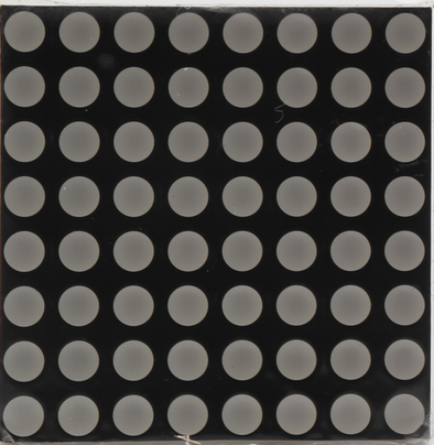
The Arduino 1088AS LED Matrix is a grid of light-emitting diodes (LEDs) that can be individually controlled to display text, images, or animations. This versatile component is widely used in applications such as digital signage, scoreboards, and decorative lighting. Its compact design and ease of integration make it a popular choice for both hobbyists and professionals.
Explore Projects Built with LED Matrix

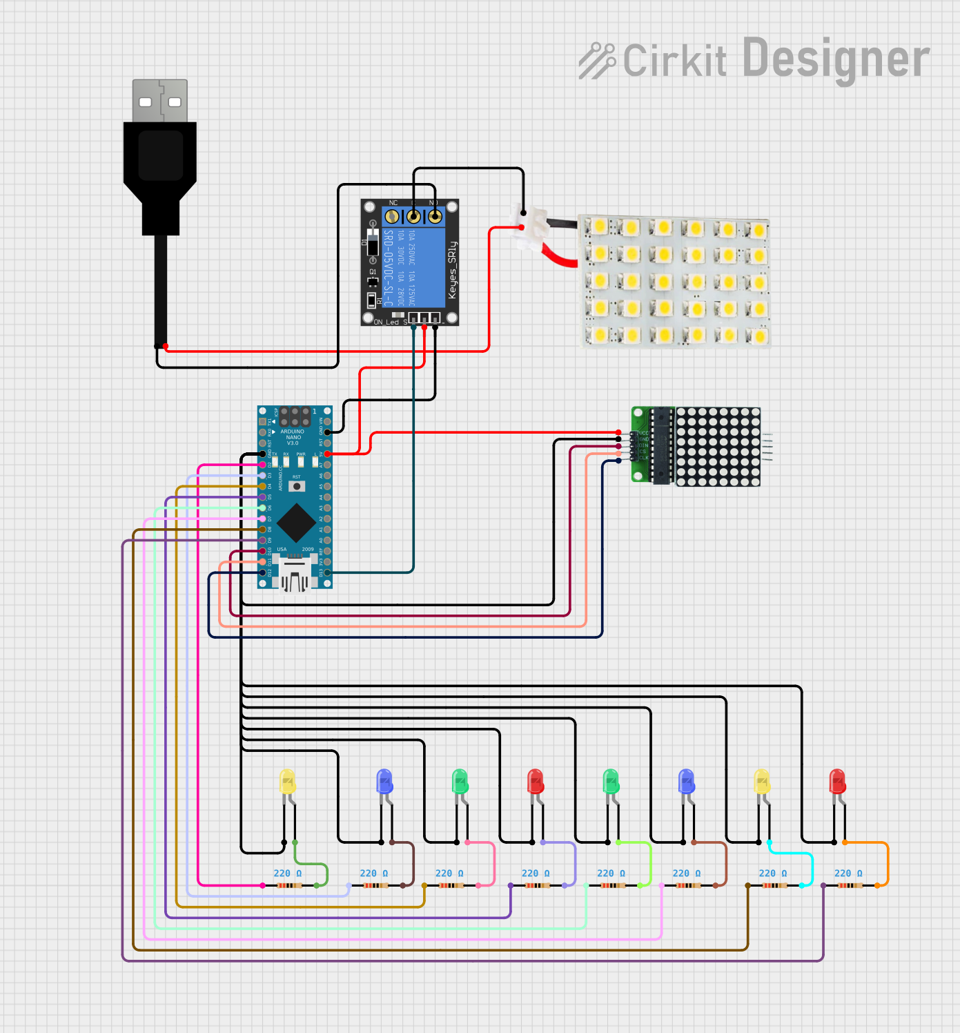


Explore Projects Built with LED Matrix
Common Applications
- Digital displays for text and numbers
- Animations and visual effects
- Scoreboards and timers
- Interactive projects and games
- IoT-based notification systems
Technical Specifications
The following table outlines the key technical details of the Arduino 1088AS LED Matrix:
| Parameter | Value |
|---|---|
| Manufacturer | Arduino |
| Part ID | 1088AS |
| LED Configuration | 8x8 grid (64 LEDs) |
| Operating Voltage | 5V |
| Forward Voltage (per LED) | 2.0V - 2.2V |
| Maximum Current (per LED) | 20mA |
| Dimensions | 32mm x 32mm x 8mm |
| LED Color | Red |
| Viewing Angle | 120° |
Pin Configuration
The 1088AS LED Matrix uses a multiplexed row-column addressing scheme. Below is the pin configuration:
| Pin Number | Description | Function |
|---|---|---|
| 1 | Row 1 (R1) | Controls the first row of LEDs |
| 2 | Row 2 (R2) | Controls the second row of LEDs |
| 3 | Row 3 (R3) | Controls the third row of LEDs |
| 4 | Row 4 (R4) | Controls the fourth row of LEDs |
| 5 | Row 5 (R5) | Controls the fifth row of LEDs |
| 6 | Row 6 (R6) | Controls the sixth row of LEDs |
| 7 | Row 7 (R7) | Controls the seventh row of LEDs |
| 8 | Row 8 (R8) | Controls the eighth row of LEDs |
| 9 | Column 1 (C1) | Controls the first column of LEDs |
| 10 | Column 2 (C2) | Controls the second column of LEDs |
| 11 | Column 3 (C3) | Controls the third column of LEDs |
| 12 | Column 4 (C4) | Controls the fourth column of LEDs |
| 13 | Column 5 (C5) | Controls the fifth column of LEDs |
| 14 | Column 6 (C6) | Controls the sixth column of LEDs |
| 15 | Column 7 (C7) | Controls the seventh column of LEDs |
| 16 | Column 8 (C8) | Controls the eighth column of LEDs |
Usage Instructions
How to Use the LED Matrix in a Circuit
- Connect the Matrix to a Microcontroller: Use an Arduino UNO or similar microcontroller to control the LED Matrix. Connect the row and column pins of the matrix to the digital I/O pins of the Arduino.
- Use a Current-Limiting Resistor: To prevent damage to the LEDs, use appropriate resistors (typically 220Ω or 330Ω) in series with the rows or columns.
- Multiplexing: The LED Matrix operates using a multiplexing technique, where only one row or column is active at a time. This requires rapid switching to create the illusion of all LEDs being lit simultaneously.
- Power Supply: Ensure the power supply can handle the total current draw of the matrix.
Example Code for Arduino UNO
Below is an example code to display a simple pattern on the 1088AS LED Matrix using an Arduino UNO:
// Example code to control the 1088AS LED Matrix with Arduino UNO
// This code lights up a diagonal pattern on the matrix

// Define the row and column pins
int rowPins[8] = {2, 3, 4, 5, 6, 7, 8, 9}; // Connect to R1-R8
int colPins[8] = {10, 11, 12, 13, A0, A1, A2, A3}; // Connect to C1-C8

void setup() {
  // Set all row pins as OUTPUT
  for (int i = 0; i < 8; i++) {
    pinMode(rowPins[i], OUTPUT);
  }

  // Set all column pins as OUTPUT
  for (int i = 0; i < 8; i++) {
    pinMode(colPins[i], OUTPUT);
  }
}

void loop() {
  // Display a diagonal pattern
  for (int i = 0; i < 8; i++) {
    // Turn on the current row
    digitalWrite(rowPins[i], LOW); // LOW activates the row

    // Turn on the corresponding column
    digitalWrite(colPins[i], HIGH); // HIGH activates the column

    delay(100); // Delay for visibility

    // Turn off the row and column
    digitalWrite(rowPins[i], HIGH);
    digitalWrite(colPins[i], LOW);
  }
}
Important Considerations
- Resistor Selection: Always use current-limiting resistors to protect the LEDs.
- Power Supply: Ensure the power supply can handle the total current draw of the matrix.
- Refresh Rate: Use a high refresh rate (e.g., 60Hz or higher) to avoid flickering.
- Heat Management: Prolonged use at high brightness may generate heat; ensure proper ventilation.
Troubleshooting and FAQs
Common Issues
LEDs Not Lighting Up
- Cause: Incorrect wiring or loose connections.
- Solution: Double-check the wiring and ensure all connections are secure.
Flickering LEDs
- Cause: Low refresh rate or insufficient power supply.
- Solution: Increase the refresh rate in the code or use a more stable power source.
Dim LEDs
- Cause: High resistance or low power supply voltage.
- Solution: Verify the resistor values and ensure the power supply provides 5V.
Overheating
- Cause: Excessive current through the LEDs.
- Solution: Use appropriate current-limiting resistors and avoid prolonged use at maximum brightness.
FAQs
Q: Can I use the 1088AS LED Matrix with other microcontrollers?
A: Yes, the 1088AS is compatible with most microcontrollers, including ESP32, Raspberry Pi, and STM32. Ensure proper pin mapping and voltage levels.
Q: How do I display custom animations?
A: Create a 2D array to represent the LED states (on/off) and update the matrix in the loop function.
Q: Can I chain multiple LED matrices together?
A: Yes, you can chain multiple matrices using shift registers or dedicated driver ICs like the MAX7219 for easier control.
Q: What is the maximum brightness of the LEDs?
A: The brightness depends on the current supplied to each LED. Avoid exceeding 20mA per LED to prevent damage.