How to Use LMP91000: Examples, Pinouts, and Specs
Introduction
The LMP91000 is a low-power, high-performance analog front-end (AFE) designed specifically for interfacing with electrochemical sensors. Manufactured by Texas Instruments, this component integrates a programmable gain amplifier (PGA), a reference voltage output, and an integrated analog-to-digital converter (ADC). These features make it ideal for applications requiring precise chemical analysis, such as gas sensing, pH measurement, and biosensing.
Explore Projects Built with LMP91000


Explore Projects Built with LMP91000
Common Applications
- Gas detection systems (e.g., CO, NO2, O2 sensors)
- pH measurement devices
- Industrial and environmental monitoring
- Medical diagnostics and biosensors
- Portable chemical analysis instruments
Technical Specifications
Key Technical Details
| Parameter | Value |
|---|---|
| Supply Voltage Range | 2.7 V to 5.25 V |
| Operating Current | 10 µA (typical) |
| Temperature Range | -40°C to +85°C |
| Programmable Gain | 2.75 kΩ to 350 kΩ |
| Reference Voltage Output | Programmable (20%, 50%, or 67% of VDD) |
| Communication Interface | I²C |
| Package Type | WSON-14 |
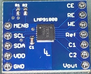
Pin Configuration and Descriptions
The LMP91000 is available in a 14-pin WSON package. Below is the pinout and description:
| Pin Number | Pin Name | Description |
|---|---|---|
| 1 | VDD | Power supply input (2.7 V to 5.25 V) |
| 2 | VREF | Reference voltage output |
| 3 | C1 | Capacitor connection for internal filtering |
| 4 | C2 | Capacitor connection for internal filtering |
| 5 | VOUT | Output voltage (connected to ADC or MCU) |
| 6 | GND | Ground |
| 7 | I2C_SCL | I²C clock line |
| 8 | I2C_SDA | I²C data line |
| 9 | TEMP | Temperature sensor output |
| 10 | CE | Counter electrode connection |
| 11 | RE | Reference electrode connection |
| 12 | WE | Working electrode connection |
| 13 | NC | No connection |
| 14 | NC | No connection |
Usage Instructions
How to Use the LMP91000 in a Circuit
- Power Supply: Connect the VDD pin to a stable power source (2.7 V to 5.25 V) and GND to ground.
- Electrochemical Sensor Connection:
- Connect the working electrode (WE), reference electrode (RE), and counter electrode (CE) of the sensor to the corresponding pins on the LMP91000.
- Reference Voltage: Use the VREF pin to set the desired reference voltage for the sensor. This can be programmed via I²C.
- Filtering: Connect appropriate capacitors to the C1 and C2 pins for internal filtering.
- Output: The VOUT pin provides the analog output signal, which can be connected to an ADC or microcontroller for further processing.
- I²C Communication: Use the I2C_SCL and I2C_SDA pins to communicate with the LMP91000. Configure the device settings (e.g., gain, reference voltage) via I²C commands.
Important Considerations and Best Practices
- Power Supply Decoupling: Place a 0.1 µF ceramic capacitor close to the VDD pin to reduce noise.
- Electrode Calibration: Calibrate the connected electrochemical sensor for accurate measurements.
- I²C Pull-Up Resistors: Use appropriate pull-up resistors (typically 4.7 kΩ) on the I²C lines.
- Temperature Compensation: Use the TEMP pin output to monitor temperature and apply compensation if necessary.
Example Code for Arduino UNO
Below is an example of how to configure the LMP91000 using an Arduino UNO via I²C:
#include <Wire.h>

// LMP91000 I2C address
#define LMP91000_ADDR 0x48

// LMP91000 register addresses
#define STATUS_REG 0x00
#define LOCK_REG   0x01
#define TIACN_REG  0x10
#define REFCN_REG  0x11

void setup() {
  Wire.begin(); // Initialize I2C communication
  Serial.begin(9600); // Initialize serial communication for debugging

  // Unlock the LMP91000 configuration registers
  writeRegister(LOCK_REG, 0x01);

  // Configure TIA gain and load resistor
  writeRegister(TIACN_REG, 0x03); // Example: 7 kΩ TIA gain, 10 Ω load resistor

  // Configure reference voltage
  writeRegister(REFCN_REG, 0x20); // Example: 50% VDD reference voltage

  // Lock the configuration registers
  writeRegister(LOCK_REG, 0x00);

  Serial.println("LMP91000 configured successfully!");
}

void loop() {
  // Add code to read sensor data and process it
}

// Function to write data to a register
void writeRegister(uint8_t reg, uint8_t value) {
  Wire.beginTransmission(LMP91000_ADDR);
  Wire.write(reg); // Register address
  Wire.write(value); // Data to write
  Wire.endTransmission();
}
Troubleshooting and FAQs
Common Issues and Solutions
No Output Signal on VOUT:
- Ensure the sensor is properly connected to the WE, RE, and CE pins.
- Verify that the LMP91000 is powered correctly (check VDD and GND connections).
- Confirm that the configuration registers are set correctly via I²C.
I²C Communication Fails:
- Check the pull-up resistors on the I²C lines (SCL and SDA).
- Verify the I²C address of the LMP91000 (default is 0x48).
- Ensure the Arduino and LMP91000 share a common ground.
Unstable Output Signal:
- Check the filtering capacitors connected to C1 and C2.
- Ensure the power supply is stable and noise-free.
- Verify the sensor calibration and environmental conditions.
FAQs
Q: Can the LMP91000 be used with a 3.3 V microcontroller?
A: Yes, the LMP91000 operates within a supply voltage range of 2.7 V to 5.25 V, making it compatible with 3.3 V systems.
Q: How do I select the TIA gain?
A: The TIA gain is configured via the TIACN register using I²C. Refer to the datasheet for the specific gain values and corresponding register settings.
Q: Is temperature compensation necessary?
A: Temperature compensation is recommended for applications where temperature variations significantly affect sensor performance. Use the TEMP pin output for this purpose.