Cirkit Designer Logo
Cirkit Designer
Your all-in-one circuit design IDE
Home / 
Component Documentation

How to Use esp32: Examples, Pinouts, and Specs

Image of esp32
Cirkit Designer LogoDesign with esp32 in Cirkit Designer

Introduction

The ESP32, manufactured by Espressif Systems, is a low-cost, low-power system on a chip (SoC) with integrated Wi-Fi and Bluetooth capabilities. It is widely used in Internet of Things (IoT) applications, embedded systems, and smart devices. The ESP32 offers a powerful dual-core processor, a rich set of peripherals, and extensive connectivity options, making it a versatile choice for developers.

Explore Projects Built with esp32

Use Cirkit Designer to design, explore, and prototype these projects online. Some projects support real-time simulation. Click "Open Project" to start designing instantly!
ESP32-Controlled OLED Display and Servo with DotStar LED Strip and Audio Output
Image of Arena 2: A project utilizing esp32 in a practical application
This circuit features an ESP32 microcontroller driving a variety of components. It controls an OLED display for visual output, a DotStar LED strip for lighting effects, a PAM8403 audio amplifier connected to a speaker for sound output, and a PCA9685 PWM Servo Breakout to manage a servo motor. The ESP32 also interfaces with a piezo speaker for additional sound generation, and the circuit is powered by a 18650 Li-ion battery setup with a TP4056 charging module. The ESP32's embedded code handles the display animation on the OLED.
Cirkit Designer LogoOpen Project in Cirkit Designer
ESP32-Based Sensor Monitoring System with OLED Display and E-Stop
Image of MVP_design: A project utilizing esp32 in a practical application
This circuit features an ESP32 microcontroller that interfaces with a variety of sensors and output devices. It is powered by a Lipo battery through a buck converter, ensuring a stable voltage supply. The ESP32 collects data from a DHT11 temperature and humidity sensor and a vibration sensor, controls a buzzer, and displays information on an OLED screen. An emergency stop (E Stop) is connected for safety purposes, allowing the system to be quickly deactivated.
Cirkit Designer LogoOpen Project in Cirkit Designer
ESP32-Based Environmental Monitoring System with Motion Detection
Image of pro: A project utilizing esp32 in a practical application
This circuit features an ESP32 microcontroller on a baseboard that interfaces with a PIR sensor for motion detection, a DHT22 sensor for measuring temperature and humidity, and a BH1750 sensor for detecting ambient light levels. The ESP32 is configured to communicate with the BH1750 using I2C protocol, with GPIO22 and GPIO21 serving as the SCL and SDA lines, respectively. Power is supplied to the sensors from the ESP32's voltage output pins, and sensor outputs are connected to designated GPIO pins for data acquisition.
Cirkit Designer LogoOpen Project in Cirkit Designer
ESP32-Based Smart Weather Station with Wi-Fi Connectivity
Image of flowchart 3D: A project utilizing esp32 in a practical application
This circuit features an ESP32 microcontroller interfacing with various sensors and modules, including a DHT22 temperature and humidity sensor, an ESP32 CAM for image capture, an I2C LCD screen for display, a load cell with an HX711 interface for weight measurement, and a buzzer for audio alerts. The ESP32 handles data acquisition, processing, and communication with these peripherals to create a multi-functional monitoring and alert system.
Cirkit Designer LogoOpen Project in Cirkit Designer

Explore Projects Built with esp32

Use Cirkit Designer to design, explore, and prototype these projects online. Some projects support real-time simulation. Click "Open Project" to start designing instantly!
Image of Arena 2: A project utilizing esp32 in a practical application
ESP32-Controlled OLED Display and Servo with DotStar LED Strip and Audio Output
This circuit features an ESP32 microcontroller driving a variety of components. It controls an OLED display for visual output, a DotStar LED strip for lighting effects, a PAM8403 audio amplifier connected to a speaker for sound output, and a PCA9685 PWM Servo Breakout to manage a servo motor. The ESP32 also interfaces with a piezo speaker for additional sound generation, and the circuit is powered by a 18650 Li-ion battery setup with a TP4056 charging module. The ESP32's embedded code handles the display animation on the OLED.
Cirkit Designer LogoOpen Project in Cirkit Designer
Image of MVP_design: A project utilizing esp32 in a practical application
ESP32-Based Sensor Monitoring System with OLED Display and E-Stop
This circuit features an ESP32 microcontroller that interfaces with a variety of sensors and output devices. It is powered by a Lipo battery through a buck converter, ensuring a stable voltage supply. The ESP32 collects data from a DHT11 temperature and humidity sensor and a vibration sensor, controls a buzzer, and displays information on an OLED screen. An emergency stop (E Stop) is connected for safety purposes, allowing the system to be quickly deactivated.
Cirkit Designer LogoOpen Project in Cirkit Designer
Image of pro: A project utilizing esp32 in a practical application
ESP32-Based Environmental Monitoring System with Motion Detection
This circuit features an ESP32 microcontroller on a baseboard that interfaces with a PIR sensor for motion detection, a DHT22 sensor for measuring temperature and humidity, and a BH1750 sensor for detecting ambient light levels. The ESP32 is configured to communicate with the BH1750 using I2C protocol, with GPIO22 and GPIO21 serving as the SCL and SDA lines, respectively. Power is supplied to the sensors from the ESP32's voltage output pins, and sensor outputs are connected to designated GPIO pins for data acquisition.
Cirkit Designer LogoOpen Project in Cirkit Designer
Image of flowchart 3D: A project utilizing esp32 in a practical application
ESP32-Based Smart Weather Station with Wi-Fi Connectivity
This circuit features an ESP32 microcontroller interfacing with various sensors and modules, including a DHT22 temperature and humidity sensor, an ESP32 CAM for image capture, an I2C LCD screen for display, a load cell with an HX711 interface for weight measurement, and a buzzer for audio alerts. The ESP32 handles data acquisition, processing, and communication with these peripherals to create a multi-functional monitoring and alert system.
Cirkit Designer LogoOpen Project in Cirkit Designer

Common Applications and Use Cases

  • IoT devices and smart home automation
  • Wearable electronics
  • Wireless sensor networks
  • Industrial automation
  • Robotics and drones
  • Prototyping and educational projects

Technical Specifications

The ESP32 Dev Module is a feature-rich development board based on the ESP32 SoC. Below are its key technical specifications:

Key Technical Details

Parameter Specification
Manufacturer Espressif Systems
Part ID ESP32 Dev Module
Processor Dual-core Xtensa® 32-bit LX6 CPU
Clock Speed Up to 240 MHz
Flash Memory 4 MB (varies by module)
SRAM 520 KB
Wi-Fi 802.11 b/g/n (2.4 GHz)
Bluetooth v4.2 BR/EDR and BLE
Operating Voltage 3.3 V
Input Voltage Range 5 V (via USB) or 3.3 V (via pins)
GPIO Pins 34
ADC Channels 18 (12-bit resolution)
DAC Channels 2 (8-bit resolution)
Communication Interfaces UART, SPI, I2C, I2S, CAN, PWM
Power Consumption Ultra-low power (varies by mode)

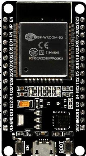
Pin Configuration and Descriptions

The ESP32 Dev Module has a variety of pins for different functionalities. Below is a summary of the pin configuration:

Pin Name Functionality Description
VIN Power Input Accepts 5 V input via USB or external source.
GND Ground Common ground for the circuit.
3V3 Power Output Provides 3.3 V output for peripherals.
EN Enable Resets the chip when pulled low.
GPIO0 Boot Mode Selection Used for flashing firmware.
GPIO2 General Purpose I/O Can be used as a standard GPIO pin.
GPIO12 ADC, Touch Sensor Supports analog input and capacitive touch.
GPIO13 PWM, ADC, Touch Sensor Supports PWM, analog input, and touch sensing.
GPIO21 I2C SDA Data line for I2C communication.
GPIO22 I2C SCL Clock line for I2C communication.
TX0 UART Transmit Transmits data via UART.
RX0 UART Receive Receives data via UART.

Note: Not all GPIO pins are available for general use. Some are reserved for specific functions or have limitations.

Usage Instructions

How to Use the ESP32 in a Circuit

  1. Powering the ESP32:

    • Connect the ESP32 to a 5 V power source via the USB port or supply 3.3 V directly to the 3V3 pin.
    • Ensure the power source can provide sufficient current (at least 500 mA).
  2. Connecting Peripherals:

    • Use the GPIO pins to connect sensors, actuators, or other peripherals.
    • For analog sensors, connect them to ADC-capable pins (e.g., GPIO12, GPIO13).
  3. Programming the ESP32:

    • Install the Arduino IDE or ESP-IDF (Espressif IoT Development Framework).
    • Select the correct board (e.g., "ESP32 Dev Module") in the IDE.
    • Connect the ESP32 to your computer via USB and upload your code.
  4. Wi-Fi and Bluetooth Setup:

    • Use the built-in libraries (e.g., WiFi.h for Wi-Fi and BluetoothSerial.h for Bluetooth) to configure connectivity.

Important Considerations and Best Practices

  • Voltage Levels: The ESP32 operates at 3.3 V logic levels. Avoid connecting 5 V signals directly to GPIO pins.
  • Boot Mode: Ensure GPIO0 is pulled low during boot to flash firmware.
  • Power Supply: Use a stable power source to avoid unexpected resets or malfunctions.
  • Heat Management: The ESP32 may heat up during operation. Ensure proper ventilation if used in enclosed spaces.

Example Code for Arduino UNO Integration

Below is an example of using the ESP32 to connect to a Wi-Fi network:

#include <WiFi.h> // Include the Wi-Fi library

// Replace with your network credentials
const char* ssid = "Your_SSID";
const char* password = "Your_PASSWORD";

void setup() {
  Serial.begin(115200); // Start serial communication at 115200 baud
  delay(1000); // Wait for a second to stabilize

  Serial.println("Connecting to Wi-Fi...");
  WiFi.begin(ssid, password); // Start Wi-Fi connection

  while (WiFi.status() != WL_CONNECTED) {
    delay(500); // Wait for connection
    Serial.print("."); // Print progress
  }

  Serial.println("\nWi-Fi connected!");
  Serial.print("IP Address: ");
  Serial.println(WiFi.localIP()); // Print the assigned IP address
}

void loop() {
  // Add your main code here
}

Note: Replace Your_SSID and Your_PASSWORD with your Wi-Fi network credentials.

Troubleshooting and FAQs

Common Issues and Solutions

  1. ESP32 Not Connecting to Wi-Fi:

    • Ensure the SSID and password are correct.
    • Check if the router is within range and supports 2.4 GHz Wi-Fi (ESP32 does not support 5 GHz).
  2. Upload Fails in Arduino IDE:

    • Verify the correct board and COM port are selected.
    • Hold the "BOOT" button on the ESP32 while uploading the code.
  3. Random Resets or Instability:

    • Use a stable power source with sufficient current.
    • Check for loose connections or short circuits.
  4. GPIO Pin Not Working:

    • Confirm the pin is not reserved for internal functions.
    • Check if the pin is configured correctly in the code.

FAQs

Q: Can the ESP32 operate on battery power?
A: Yes, the ESP32 can be powered by a battery. Use a 3.7 V LiPo battery with a voltage regulator to provide 3.3 V.

Q: How do I reset the ESP32?
A: Press the "EN" button on the module to reset the ESP32.

Q: Can I use the ESP32 with 5 V logic devices?
A: No, the ESP32 operates at 3.3 V logic levels. Use a level shifter for compatibility with 5 V devices.