
How to Use ESP32 WROOM-32U: Examples, Pinouts, and Specs
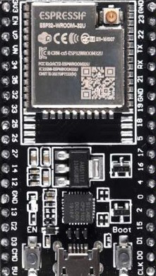
 Design with ESP32 WROOM-32U in Cirkit Designer
Introduction
The ESP32 WROOM-32U, manufactured by Espressif, is a powerful and versatile microcontroller module designed for Internet of Things (IoT) applications. It features integrated Wi-Fi and Bluetooth capabilities, making it ideal for wireless communication projects. With its dual-core processing power, extensive GPIO options, and compact design, the ESP32 WROOM-32U is suitable for a wide range of applications, including smart home devices, industrial automation, wearable electronics, and more.
Explore Projects Built with ESP32 WROOM-32U
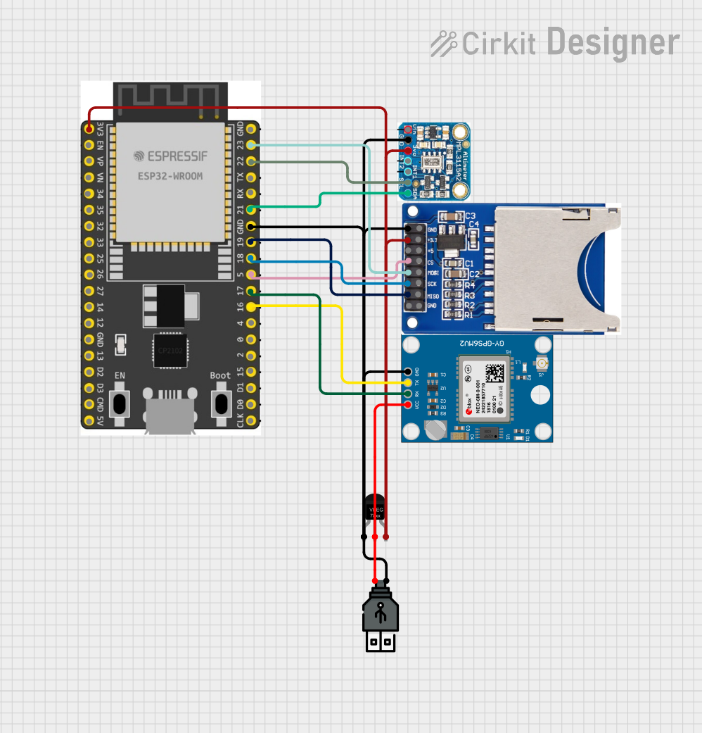 Open Project in Cirkit Designer
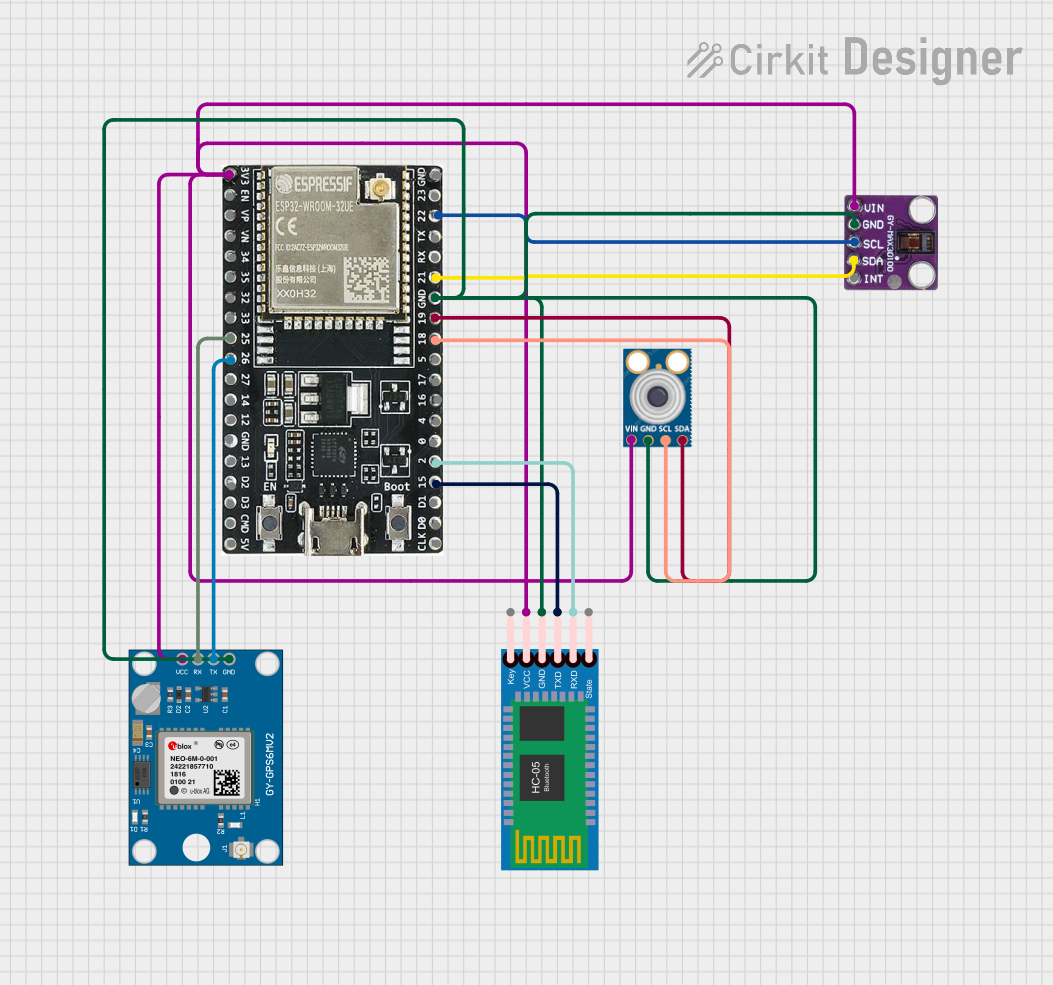 Open Project in Cirkit Designer
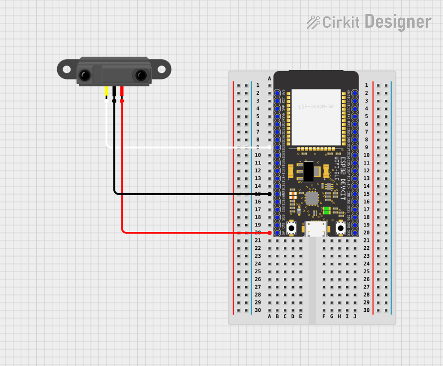 Open Project in Cirkit Designer
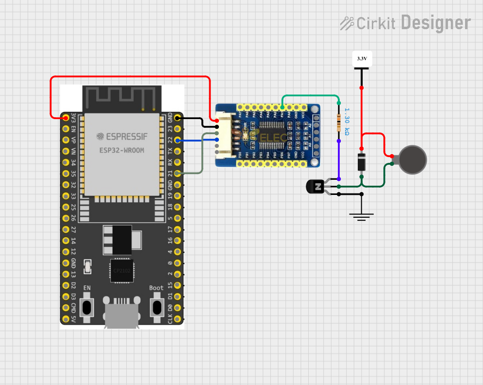 Open Project in Cirkit Designer
Explore Projects Built with ESP32 WROOM-32U
Open Project in Cirkit DesignerOpen Project in Cirkit DesignerOpen Project in Cirkit DesignerOpen Project in Cirkit DesignerCommon Applications
- IoT devices and smart home systems
- Wireless sensor networks
- Industrial automation and control systems
- Wearable technology
- Robotics and embedded systems
- Prototyping and development of wireless communication projects
Technical Specifications
Key Technical Details
| Parameter | Specification |
|---|---|
| Manufacturer | Espressif |
| Part Number | WROOM-32U |
| Microcontroller | ESP32-D0WD |
| Wireless Connectivity | Wi-Fi (802.11 b/g/n), Bluetooth v4.2 + BLE |
| CPU | Dual-core Xtensa® 32-bit LX6, up to 240 MHz |
| Flash Memory | 4 MB (external SPI flash) |
| SRAM | 520 KB |
| Operating Voltage | 3.0V to 3.6V |
| GPIO Pins | 36 (multipurpose, including ADC, DAC, PWM, etc.) |
| ADC Channels | 18 (12-bit resolution) |
| DAC Channels | 2 |
| Communication Interfaces | UART, SPI, I2C, I2S, CAN, PWM |
| Power Consumption | Ultra-low power in deep sleep mode (~10 µA) |
| Dimensions | 18 mm x 25.5 mm |
Pin Configuration and Descriptions
The ESP32 WROOM-32U has 38 pins, with 36 GPIOs that can be configured for various functions. Below is a summary of the pin configuration:
| Pin Number | Pin Name | Description |
|---|---|---|
| 1 | EN | Enable pin (active high, resets the module) |
| 2 | IO0 | GPIO0, used for boot mode selection |
| 3 | IO1 | GPIO1, UART TXD0 |
| 4 | IO2 | GPIO2, supports PWM, ADC, etc. |
| 5 | IO3 | GPIO3, UART RXD0 |
| ... | ... | ... |
| 36 | IO35 | GPIO35, ADC input only |
| 37 | GND | Ground |
| 38 | 3V3 | 3.3V power supply |
Note: For the full pinout and alternate functions, refer to the official datasheet.
Usage Instructions
How to Use the ESP32 WROOM-32U in a Circuit
- Power Supply: Provide a stable 3.3V power supply to the module. Avoid exceeding 3.6V to prevent damage.
- Boot Mode: Connect GPIO0 to GND during power-up to enter bootloader mode for programming.
- Programming: Use a USB-to-serial adapter (e.g., FTDI or CP2102) to upload code via UART0 (TXD0 and RXD0).
- GPIO Usage: Configure GPIO pins as input, output, or alternate functions (e.g., ADC, PWM) in your code.
- Antenna: The WROOM-32U uses an external antenna. Ensure proper antenna connection for optimal wireless performance.
Important Considerations
- Deep Sleep Mode: Use deep sleep mode to minimize power consumption in battery-powered applications.
- Voltage Levels: Ensure all GPIO inputs are within the 0V to 3.3V range to avoid damage.
- External Components: Add decoupling capacitors near the power pins to reduce noise and improve stability.
- Antenna Placement: Place the external antenna away from metal objects or other sources of interference.
Example Code for Arduino UNO
The ESP32 WROOM-32U can be programmed using the Arduino IDE. Below is an example of a basic Wi-Fi connection:
#include <WiFi.h> // Include the Wi-Fi library

// Replace with your network credentials
const char* ssid = "Your_SSID";
const char* password = "Your_PASSWORD";

void setup() {
  Serial.begin(115200); // Initialize serial communication
  delay(1000);

  Serial.println("Connecting to Wi-Fi...");
  WiFi.begin(ssid, password); // Start Wi-Fi connection

  while (WiFi.status() != WL_CONNECTED) {
    delay(500);
    Serial.print("."); // Print dots while connecting
  }

  Serial.println("\nWi-Fi connected!");
  Serial.print("IP Address: ");
  Serial.println(WiFi.localIP()); // Print the assigned IP address
}

void loop() {
  // Add your main code here
}
Note: Install the ESP32 board package in the Arduino IDE before uploading the code.
Troubleshooting and FAQs
Common Issues
Module Not Responding
- Cause: Incorrect power supply or wiring.
- Solution: Ensure a stable 3.3V power supply and verify all connections.
Wi-Fi Connection Fails
- Cause: Incorrect SSID or password.
- Solution: Double-check the network credentials in your code.
Code Upload Fails
- Cause: Incorrect boot mode or serial port settings.
- Solution: Hold GPIO0 low during power-up and select the correct COM port in the IDE.
GPIO Pin Not Working
- Cause: Pin conflict or incorrect configuration.
- Solution: Verify the pin's alternate functions and ensure proper initialization in the code.
FAQs
Q: Can the ESP32 WROOM-32U operate on 5V?
A: No, the module operates on 3.3V. Use a voltage regulator if your power source is 5V.Q: How do I reset the module?
A: Pull the EN pin low momentarily to reset the module.Q: Can I use the ESP32 WROOM-32U with an external antenna?
A: Yes, the WROOM-32U is designed for use with an external antenna. Ensure proper connection for optimal performance.Q: Is the module compatible with Arduino libraries?
A: Yes, the ESP32 is supported by the Arduino IDE and many libraries are available for it.
This concludes the documentation for the ESP32 WROOM-32U. For further details, refer to the official Espressif datasheet and resources.