Cirkit Designer
Your all-in-one circuit design IDE
Home /
Component Documentation
How to Use L298N DC motor driver: Examples, Pinouts, and Specs
Introduction
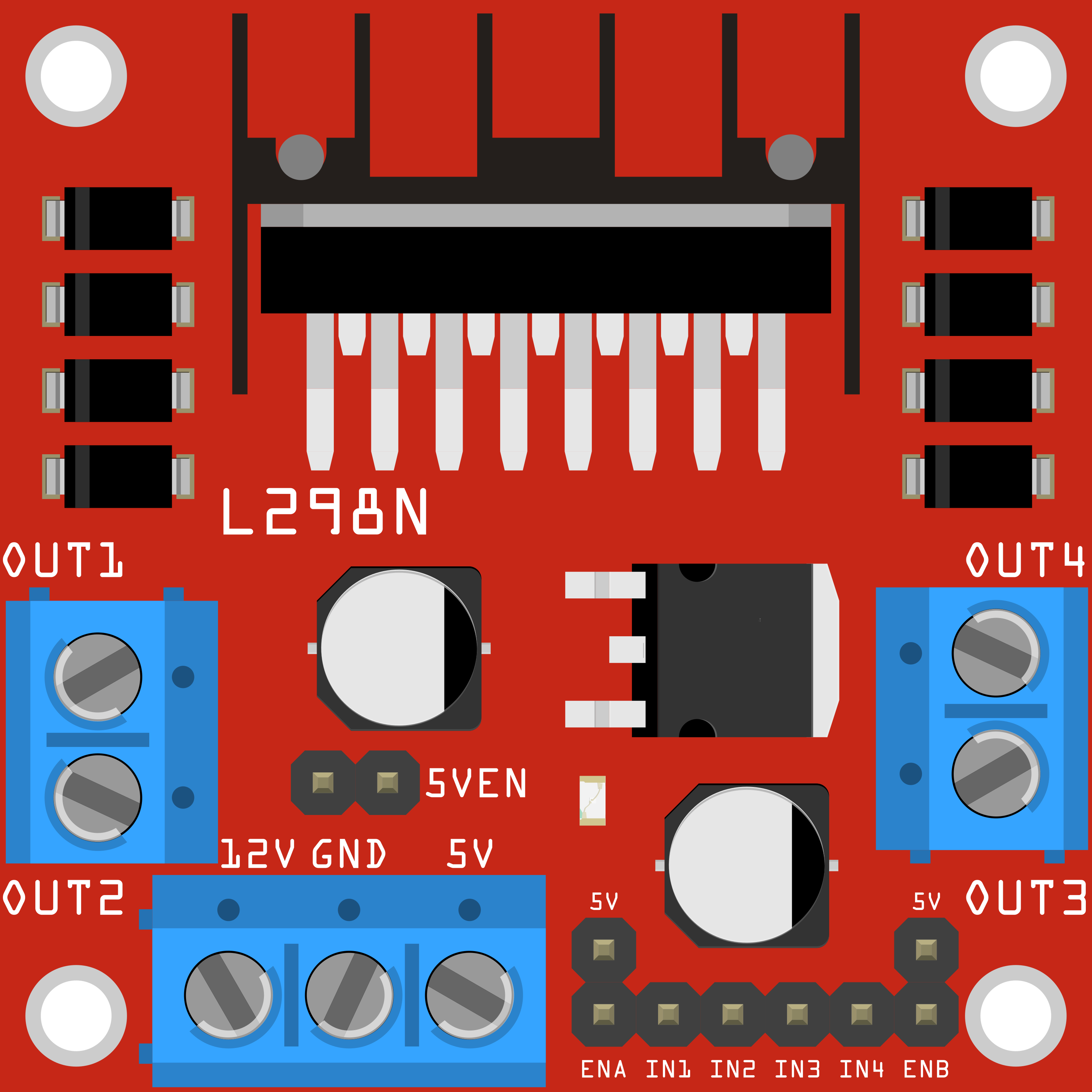
The L298N DC Motor Driver Module, manufactured by JJY (Part ID: L298N_Module), is a versatile and robust dual H-bridge motor driver. It allows for the control of the speed and direction of two DC motors independently. With a current handling capacity of up to 2A per channel, this module is ideal for a wide range of applications, including robotics, automation projects, and any other project requiring precise motor control.
Explore Projects Built with L298N DC motor driver
L298N DC Motor Driver Controlled DC Motor System
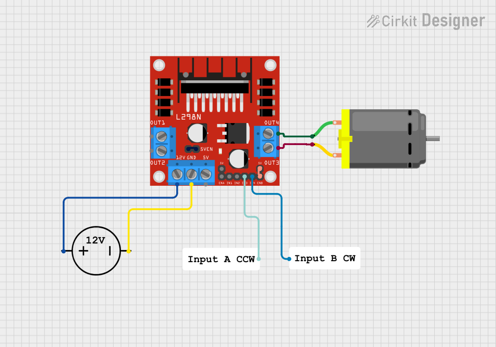
This circuit is designed to control a DC motor using an L298N motor driver module. The motor driver is powered by a DC power source and interfaces with the motor through its output pins, while resistors are used to manage the input signals to the driver.
Wi-Fi Controlled Quad DC Motor Driver System
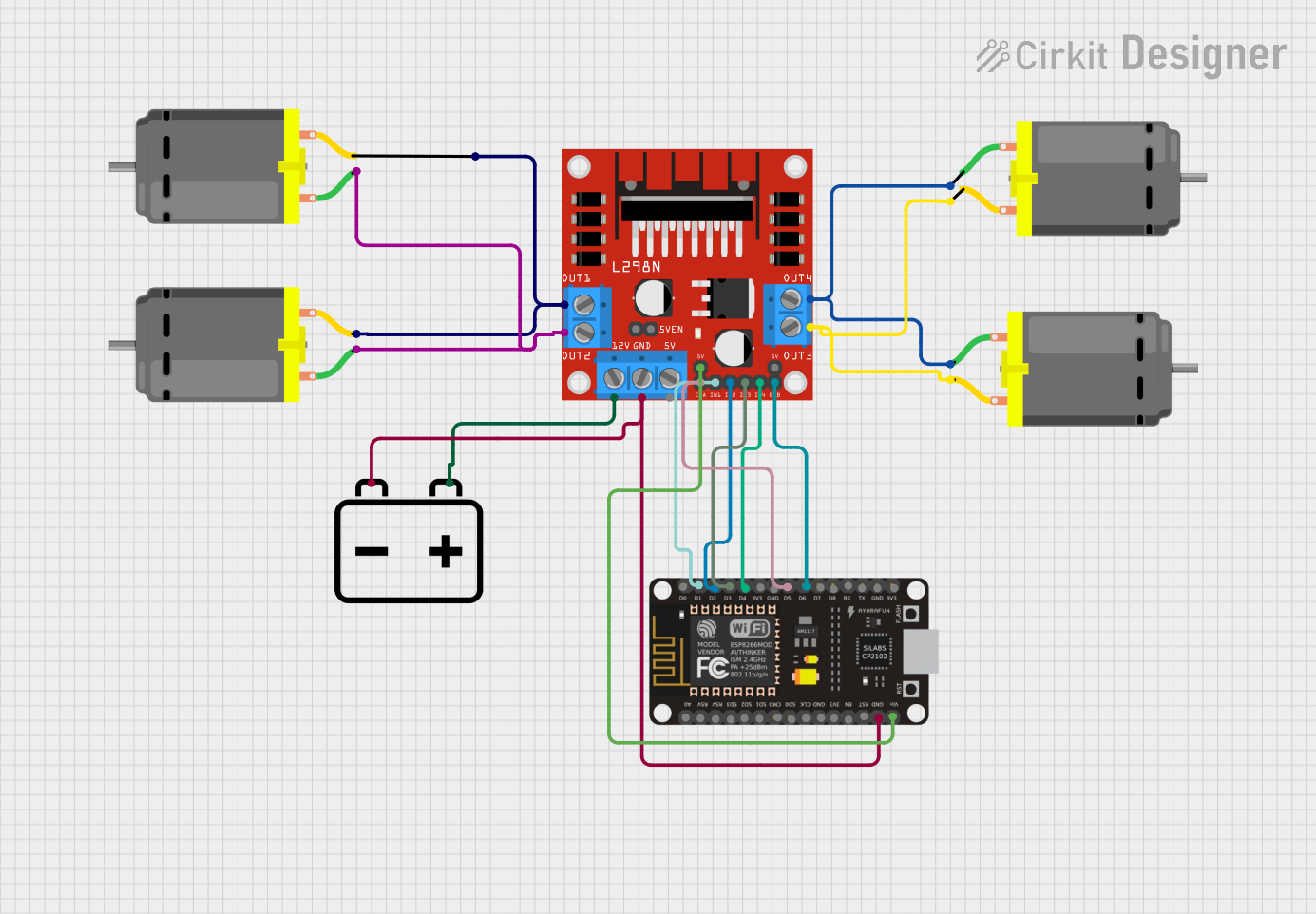
This circuit is designed to control four DC motors using an L298N motor driver module, which is interfaced with an ESP8266 NodeMCU microcontroller. The NodeMCU's digital pins (D1-D6) are connected to the input pins of the L298N to control the speed and direction of the motors. A 12V battery provides power to the motors through the motor driver, and also powers the NodeMCU through a voltage regulator on the L298N.
Arduino and L298N Motor Driver Controlled DC Motor System
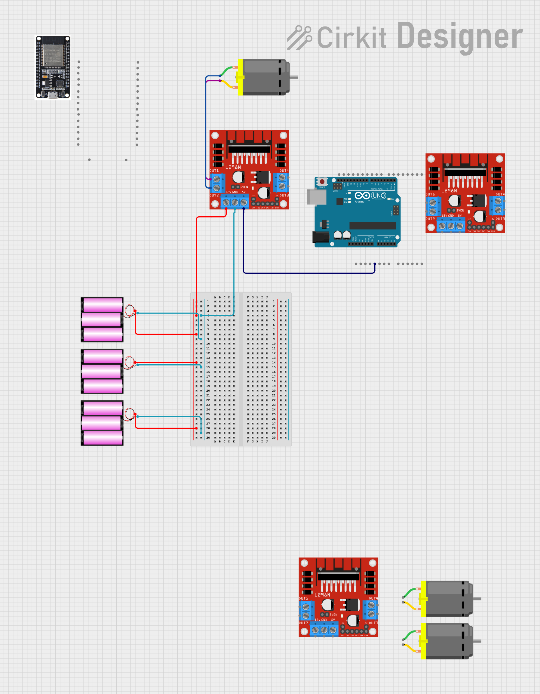
This circuit controls a DC motor using an L298N motor driver module, powered by three 12V batteries. An Arduino UNO is used to provide 5V power to the motor driver and can be programmed to control the motor's operation.
Arduino-Controlled Fire Detection and GSM Notification System
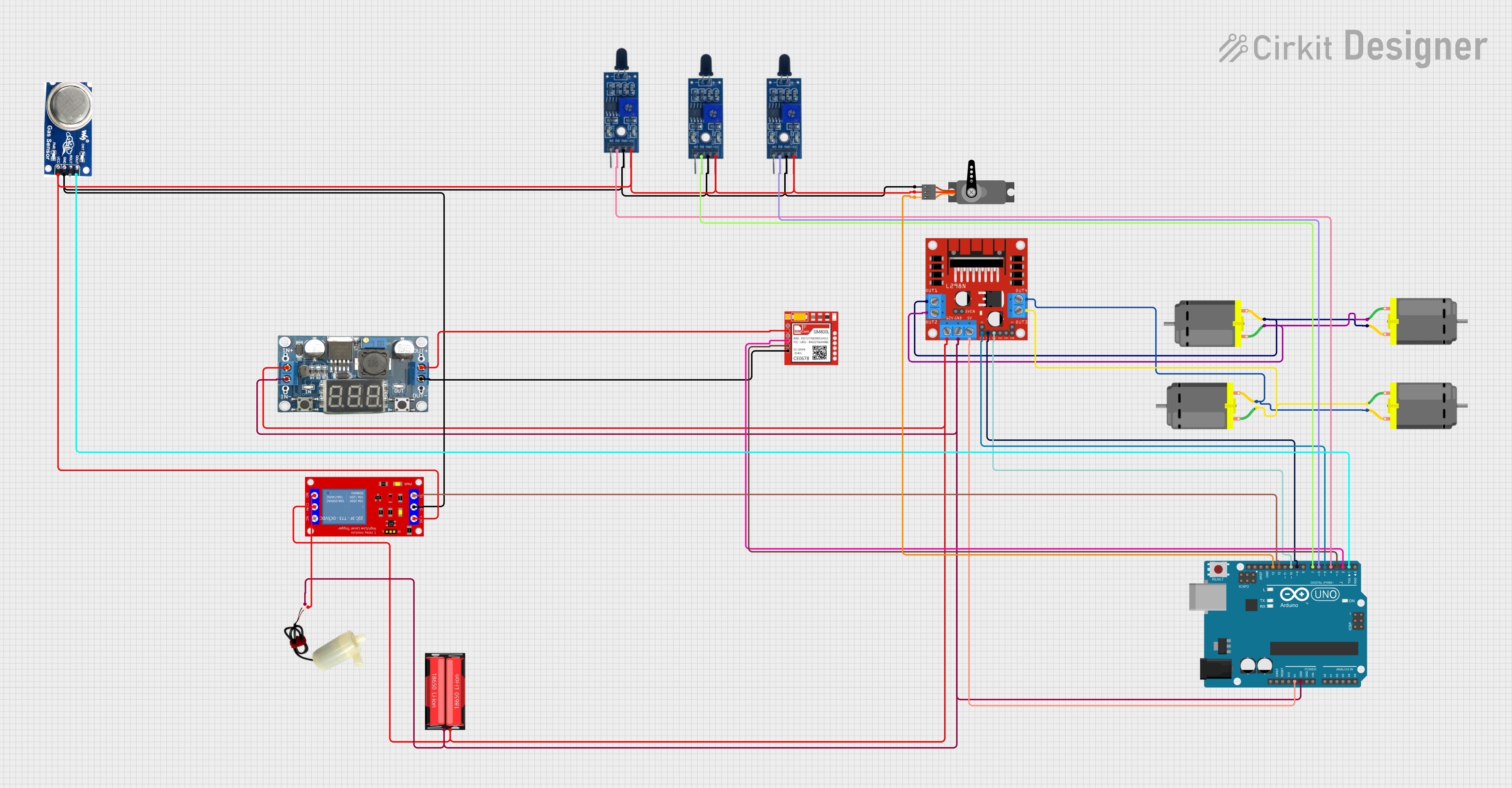
This circuit is designed to control multiple DC motors using an L298N motor driver, which is interfaced with an Arduino UNO microcontroller. The Arduino controls the direction and speed of the motors, as well as a servo motor, and can activate a water pump via a relay module. Additionally, the circuit includes flame and smoke sensors for safety monitoring, and a SIM800L module for potential communication capabilities.
Explore Projects Built with L298N DC motor driver
L298N DC Motor Driver Controlled DC Motor System
This circuit is designed to control a DC motor using an L298N motor driver module. The motor driver is powered by a DC power source and interfaces with the motor through its output pins, while resistors are used to manage the input signals to the driver.
Wi-Fi Controlled Quad DC Motor Driver System
This circuit is designed to control four DC motors using an L298N motor driver module, which is interfaced with an ESP8266 NodeMCU microcontroller. The NodeMCU's digital pins (D1-D6) are connected to the input pins of the L298N to control the speed and direction of the motors. A 12V battery provides power to the motors through the motor driver, and also powers the NodeMCU through a voltage regulator on the L298N.
Arduino and L298N Motor Driver Controlled DC Motor System
This circuit controls a DC motor using an L298N motor driver module, powered by three 12V batteries. An Arduino UNO is used to provide 5V power to the motor driver and can be programmed to control the motor's operation.
Arduino-Controlled Fire Detection and GSM Notification System
This circuit is designed to control multiple DC motors using an L298N motor driver, which is interfaced with an Arduino UNO microcontroller. The Arduino controls the direction and speed of the motors, as well as a servo motor, and can activate a water pump via a relay module. Additionally, the circuit includes flame and smoke sensors for safety monitoring, and a SIM800L module for potential communication capabilities.
Technical Specifications
Key Technical Details
| Parameter | Value |
|---|---|
| Operating Voltage | 5V to 35V |
| Output Current | 2A per channel (max 3A peak) |
| Control Logic | Standard TTL logic levels |
| Power Dissipation | 25W |
| Dimensions | 43mm x 43mm x 27mm |
| Weight | 26g |
Pin Configuration and Descriptions
| Pin Number | Pin Name | Description |
|---|---|---|
| 1 | ENA | Enable pin for Motor A (High to enable) |
| 2 | IN1 | Input 1 for Motor A (connected to microcontroller) |
| 3 | IN2 | Input 2 for Motor A (connected to microcontroller) |
| 4 | OUT1 | Output 1 for Motor A (connected to motor terminal) |
| 5 | OUT2 | Output 2 for Motor A (connected to motor terminal) |
| 6 | GND | Ground |
| 7 | VCC | Supply voltage for the motor (5V to 35V) |
| 8 | ENB | Enable pin for Motor B (High to enable) |
| 9 | IN3 | Input 3 for Motor B (connected to microcontroller) |
| 10 | IN4 | Input 4 for Motor B (connected to microcontroller) |
| 11 | OUT3 | Output 3 for Motor B (connected to motor terminal) |
| 12 | OUT4 | Output 4 for Motor B (connected to motor terminal) |
| 13 | 5V | 5V output (can be used to power the logic circuitry of the microcontroller) |
Usage Instructions
How to Use the Component in a Circuit
Power Connections:
- Connect the
VCCpin to the power supply (5V to 35V) for the motors. - Connect the
GNDpin to the ground of the power supply.
- Connect the
Motor Connections:
- Connect the motor terminals to
OUT1andOUT2for Motor A. - Connect the motor terminals to
OUT3andOUT4for Motor B.
- Connect the motor terminals to
Control Connections:
- Connect
ENAto a PWM-capable pin on the microcontroller to control the speed of Motor A. - Connect
ENBto a PWM-capable pin on the microcontroller to control the speed of Motor B. - Connect
IN1andIN2to digital pins on the microcontroller to control the direction of Motor A. - Connect
IN3andIN4to digital pins on the microcontroller to control the direction of Motor B.
- Connect
Important Considerations and Best Practices
- Ensure that the power supply voltage does not exceed the maximum rating of 35V.
- Use appropriate heat sinks or cooling mechanisms if the module is expected to operate at high currents for extended periods.
- Double-check all connections before powering up the module to avoid short circuits or damage to the components.
Example Code for Arduino UNO
// Define motor control pins
#define ENA 9
#define IN1 8
#define IN2 7
#define ENB 10
#define IN3 6
#define IN4 5

void setup() {
  // Set all the motor control pins to output
  pinMode(ENA, OUTPUT);
  pinMode(IN1, OUTPUT);
  pinMode(IN2, OUTPUT);
  pinMode(ENB, OUTPUT);
  pinMode(IN3, OUTPUT);
  pinMode(IN4, OUTPUT);
}

void loop() {
  // Example: Rotate Motor A forward at full speed
  digitalWrite(IN1, HIGH);
  digitalWrite(IN2, LOW);
  analogWrite(ENA, 255); // Full speed

  // Example: Rotate Motor B backward at half speed
  digitalWrite(IN3, LOW);
  digitalWrite(IN4, HIGH);
  analogWrite(ENB, 128); // Half speed

  delay(2000); // Run motors for 2 seconds

  // Stop both motors
  analogWrite(ENA, 0);
  analogWrite(ENB, 0);

  delay(2000); // Wait for 2 seconds before repeating
}
Troubleshooting and FAQs
Common Issues Users Might Face
Motors Not Running:
- Ensure that the
ENAandENBpins are set high or connected to PWM signals. - Check the power supply connections and ensure the voltage is within the specified range.
- Verify that the motor connections are correct and secure.
- Ensure that the
Overheating:
- Ensure that the current drawn by the motors does not exceed the module's rating.
- Use heat sinks or cooling fans if necessary.
Erratic Motor Behavior:
- Check for loose connections or short circuits.
- Ensure that the control signals from the microcontroller are stable and within the correct logic levels.
Solutions and Tips for Troubleshooting
- Double-Check Connections: Always verify that all connections are secure and correctly placed.
- Use Proper Power Supply: Ensure that the power supply can provide sufficient current for the motors.
- Monitor Temperature: If the module gets too hot, consider adding heat sinks or reducing the load.
By following this documentation, users should be able to effectively utilize the L298N DC Motor Driver Module in their projects, ensuring reliable and efficient motor control.