How to Use Faulhaber Encoder Header: Examples, Pinouts, and Specs
Introduction
The Faulhaber Encoder Header is a specialized connector designed to interface with Faulhaber encoders. These encoders are precision devices that convert rotational position or motion into electrical signals, providing critical feedback for motion control systems. The encoder header ensures reliable electrical connections between the encoder and the control electronics, enabling accurate and efficient operation in various applications.
Explore Projects Built with Faulhaber Encoder Header


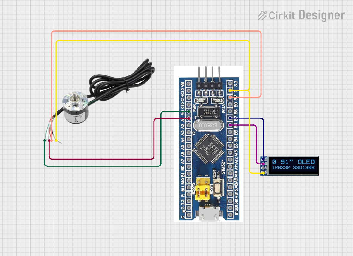
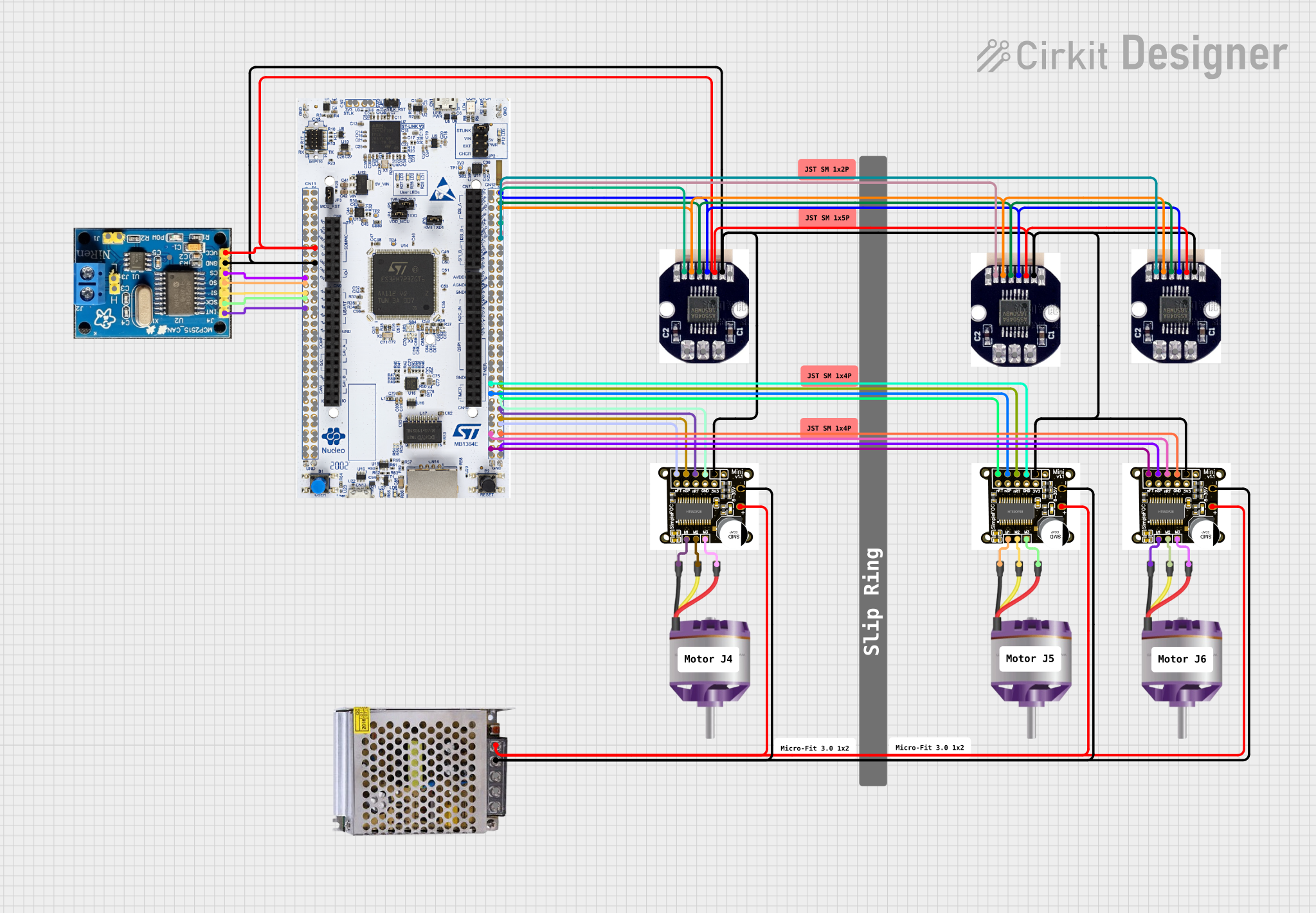
Explore Projects Built with Faulhaber Encoder Header
Common Applications and Use Cases
- Robotics: For precise motor control and position feedback.
- Industrial Automation: Used in conveyor systems, CNC machines, and robotic arms.
- Medical Devices: Ensures accurate motion control in surgical robots and diagnostic equipment.
- Aerospace: Provides feedback for actuators and control systems.
- Research and Development: Used in prototyping and testing of motion control systems.
Technical Specifications
Key Technical Details
- Manufacturer: Faulhaber
- Connector Type: Header
- Number of Pins: Typically 6 or 8 (depending on encoder model)
- Voltage Rating: 5V DC (standard for most encoders)
- Current Rating: 100 mA (per pin, typical)
- Operating Temperature: -40°C to +85°C
- Material: Gold-plated contacts for reliable signal transmission and corrosion resistance
- Mounting Style: Through-hole or surface-mount, depending on the model
Pin Configuration and Descriptions
The pin configuration may vary depending on the specific encoder model. Below is a typical 6-pin configuration for a Faulhaber Encoder Header:
| Pin Number | Name | Description |
|---|---|---|
| 1 | VCC | Power supply input (typically 5V DC). |
| 2 | GND | Ground connection. |
| 3 | A+ | Channel A positive signal (quadrature encoder output). |
| 4 | B+ | Channel B positive signal (quadrature encoder output). |
| 5 | Index (Z) | Index pulse signal for absolute position reference (optional, depending on model). |
| 6 | Shield/Ground | Shielding or additional ground connection for noise reduction. |
For an 8-pin configuration, additional pins may include differential signals (A-, B-, Z-) for enhanced noise immunity.
Usage Instructions
How to Use the Component in a Circuit
- Identify the Encoder Model: Verify the pinout and specifications of the Faulhaber encoder you are using.
- Connect the Header: Solder the Faulhaber Encoder Header to your PCB or use a compatible connector.
- Power the Encoder: Connect the VCC pin to a 5V DC power source and the GND pin to the ground.
- Connect Signal Pins: Interface the A+, B+, and optional Z signals to your microcontroller or motion controller.
- Shielding: If available, connect the shield pin to the ground to minimize electrical noise.
Important Considerations and Best Practices
- Voltage Compatibility: Ensure the encoder and header are powered with the correct voltage (typically 5V DC).
- Signal Integrity: Use short, shielded cables to reduce noise and signal degradation.
- Differential Signals: For long cable runs or noisy environments, use differential signal pairs (A+/A-, B+/B-, Z+/Z-).
- Mounting: Secure the header firmly to avoid loose connections during operation.
- Testing: Verify connections with a multimeter before powering the circuit.
Example: Connecting to an Arduino UNO
Below is an example of how to connect a Faulhaber Encoder Header to an Arduino UNO for reading encoder signals:
// Example code to read Faulhaber encoder signals using Arduino UNO
// Connect A+ to pin 2, B+ to pin 3, and GND to Arduino GND

#define ENCODER_PIN_A 2  // Pin connected to A+ signal
#define ENCODER_PIN_B 3  // Pin connected to B+ signal

volatile int encoderPosition = 0;  // Variable to store encoder position
volatile bool lastAState = LOW;    // Last state of A+ signal

void setup() {
  pinMode(ENCODER_PIN_A, INPUT);  // Set A+ pin as input
  pinMode(ENCODER_PIN_B, INPUT);  // Set B+ pin as input
  attachInterrupt(digitalPinToInterrupt(ENCODER_PIN_A), readEncoder, CHANGE);
  Serial.begin(9600);  // Initialize serial communication
}

void loop() {
  // Print the encoder position to the Serial Monitor
  Serial.println(encoderPosition);
  delay(100);  // Delay for readability
}

void readEncoder() {
  // Interrupt service routine to handle encoder signals
  bool currentAState = digitalRead(ENCODER_PIN_A);
  bool currentBState = digitalRead(ENCODER_PIN_B);

  // Determine direction based on A+ and B+ signals
  if (currentAState != lastAState) {
    if (currentAState == HIGH) {
      if (currentBState == LOW) {
        encoderPosition++;  // Clockwise rotation
      } else {
        encoderPosition--;  // Counterclockwise rotation
      }
    }
  }
  lastAState = currentAState;  // Update last state
}
Troubleshooting and FAQs
Common Issues and Solutions
No Signal Detected:
- Cause: Incorrect wiring or loose connections.
- Solution: Double-check the pinout and ensure all connections are secure.
Erratic or Noisy Signals:
- Cause: Electrical noise or long, unshielded cables.
- Solution: Use shielded cables and connect the shield pin to ground.
Incorrect Position Readings:
- Cause: Misaligned encoder or incorrect signal interpretation.
- Solution: Verify encoder alignment and check the decoding logic in your code.
Overheating:
- Cause: Exceeding voltage or current ratings.
- Solution: Ensure the power supply matches the encoder's specifications.
FAQs
Q: Can I use the Faulhaber Encoder Header with a 3.3V system?
A: Most Faulhaber encoders require 5V. Check your encoder's datasheet for compatibility with 3.3V systems.Q: What is the purpose of the Index (Z) signal?
A: The Index signal provides a single pulse per revolution, useful for absolute position referencing.Q: How do I extend the cable length without signal loss?
A: Use shielded, twisted-pair cables and differential signals (if supported) to minimize noise and signal degradation.Q: Can I use this header for non-Faulhaber encoders?
A: While possible, ensure the pinout and electrical specifications match the encoder you are using.