How to Use ESP32: Examples, Pinouts, and Specs
Introduction
The ESP32 is a powerful, low-cost microcontroller with integrated Wi-Fi and Bluetooth capabilities, making it an excellent choice for Internet of Things (IoT) applications and embedded systems. Developed by Espressif Systems, the ESP32 is widely used in smart home devices, wearable electronics, industrial automation, and more. Its dual-core processor, extensive GPIO options, and support for various communication protocols make it a versatile and efficient solution for a wide range of projects.
Explore Projects Built with ESP32


Explore Projects Built with ESP32
Common Applications
- IoT devices (e.g., smart home automation, sensors, and actuators)
- Wearable electronics
- Wireless communication systems
- Industrial automation and control
- Robotics and drones
- Prototyping and educational projects
Technical Specifications
The ESP32 is packed with features that make it a standout microcontroller for modern applications. Below are its key technical specifications:
General Specifications
- Processor: Dual-core Xtensa® 32-bit LX6 microprocessor
- Clock Speed: Up to 240 MHz
- RAM: 520 KB SRAM
- Flash Memory: Typically 4 MB (varies by module)
- Wi-Fi: 802.11 b/g/n (2.4 GHz)
- Bluetooth: v4.2 BR/EDR and BLE
- Operating Voltage: 3.0V to 3.6V
- GPIO Pins: 34 (multipurpose, including ADC, DAC, PWM, I2C, SPI, UART)
- ADC Resolution: 12-bit
- DAC Resolution: 8-bit
- Power Consumption: Ultra-low power consumption with multiple power modes
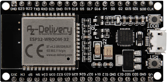
Pin Configuration
The ESP32 has a variety of pins for different functionalities. Below is a table summarizing the key pin configurations:
| Pin Name | Function | Description |
|---|---|---|
| GPIO0 | Input/Output, Boot Mode Select | Used for general I/O or to select boot mode during startup. |
| GPIO2 | Input/Output, ADC, DAC | General-purpose I/O, supports ADC and DAC functionality. |
| GPIO12 | Input/Output, ADC, Touch Sensor | General-purpose I/O, supports ADC and capacitive touch sensing. |
| GPIO13 | Input/Output, PWM, Touch Sensor | General-purpose I/O, supports PWM and capacitive touch sensing. |
| GPIO21 | Input/Output, I2C SDA | General-purpose I/O, often used as the I2C data line (SDA). |
| GPIO22 | Input/Output, I2C SCL | General-purpose I/O, often used as the I2C clock line (SCL). |
| GPIO23 | Input/Output, SPI MOSI | General-purpose I/O, often used as the SPI Master Out Slave In (MOSI) line. |
| EN | Enable | Active-high enable pin to reset the chip. |
| VIN | Power Input | Input voltage (5V) for powering the ESP32. |
| GND | Ground | Ground connection. |
Note: The exact pinout may vary depending on the ESP32 module or development board you are using (e.g., ESP32-WROOM-32, ESP32-WROVER).
Usage Instructions
The ESP32 is highly versatile and can be used in a variety of circuits and applications. Below are the steps and best practices for using the ESP32 in your projects.
Basic Setup
Powering the ESP32:
- The ESP32 can be powered via the VIN pin (5V) or through the micro-USB port on development boards.
- Ensure the input voltage is within the operating range (3.0V to 3.6V for the chip, 5V for development boards).
Programming the ESP32:
- The ESP32 can be programmed using the Arduino IDE, Espressif's ESP-IDF, or other compatible environments.
- Install the necessary drivers and libraries for your development environment.
Connecting to Wi-Fi:
- Use the built-in Wi-Fi module to connect to a network. Below is an example Arduino sketch for connecting to Wi-Fi:
#include <WiFi.h> // Include the WiFi library for ESP32

const char* ssid = "Your_SSID";       // Replace with your Wi-Fi network name
const char* password = "Your_Password"; // Replace with your Wi-Fi password

void setup() {
  Serial.begin(115200); // Initialize serial communication at 115200 baud
  WiFi.begin(ssid, password); // Start Wi-Fi connection

  Serial.print("Connecting to Wi-Fi");
  while (WiFi.status() != WL_CONNECTED) {
    delay(500); // Wait for connection
    Serial.print(".");
  }
  Serial.println("\nConnected to Wi-Fi!");
  Serial.print("IP Address: ");
  Serial.println(WiFi.localIP()); // Print the assigned IP address
}

void loop() {
  // Add your main code here
}
Important Considerations
- GPIO Voltage Levels: The ESP32 operates at 3.3V logic levels. Avoid connecting 5V signals directly to GPIO pins.
- Power Supply: Use a stable power source to avoid unexpected resets or instability.
- Boot Mode: Ensure GPIO0 is pulled low during boot to enter programming mode.
- Heat Management: The ESP32 may generate heat during operation. Ensure proper ventilation if used in enclosed spaces.
Troubleshooting and FAQs
Common Issues
ESP32 Not Connecting to Wi-Fi:
- Cause: Incorrect SSID or password.
- Solution: Double-check the credentials in your code. Ensure the Wi-Fi network is active and within range.
ESP32 Not Detected by Computer:
- Cause: Missing drivers or faulty USB cable.
- Solution: Install the correct USB-to-serial drivers (e.g., CP210x or CH340). Try a different USB cable.
Random Resets or Instability:
- Cause: Insufficient power supply or voltage fluctuations.
- Solution: Use a stable power source and ensure proper decoupling capacitors are in place.
GPIO Pin Not Responding:
- Cause: Pin conflict or incorrect configuration.
- Solution: Verify the pin's function and ensure it is not being used for another purpose (e.g., boot mode).
FAQs
Q: Can the ESP32 be powered with 5V?
A: Yes, but only through the VIN pin or the USB port. The GPIO pins operate at 3.3V logic levels.Q: How do I reset the ESP32?
A: Press the "EN" button on the development board or toggle the EN pin.Q: Can the ESP32 run on battery power?
A: Yes, the ESP32 supports battery operation. Use a 3.7V LiPo battery with a suitable voltage regulator.Q: Is the ESP32 compatible with Arduino libraries?
A: Yes, many Arduino libraries are compatible with the ESP32, but some may require modifications.
By following this documentation, you can effectively integrate the ESP32 into your projects and troubleshoot common issues. Happy building!