
How to Use Adafruit AD8495: Examples, Pinouts, and Specs
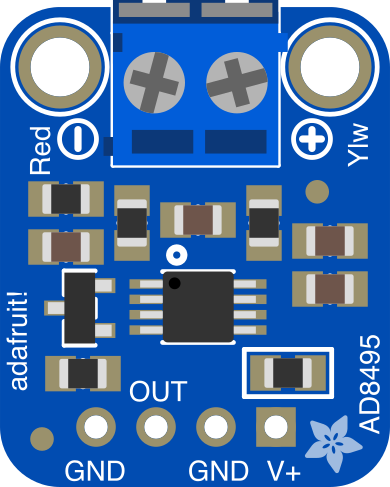
 Design with Adafruit AD8495 in Cirkit Designer
Introduction
The Adafruit AD8495 (Manufacturer Part ID: 1778) is a precision thermocouple amplifier designed to interface with thermocouples, such as K-type or J-type, and provide a linear output voltage proportional to the measured temperature. This component simplifies the process of temperature sensing by amplifying the small voltage generated by thermocouples and converting it into a readable analog signal. Its low noise design ensures accurate and stable temperature readings, making it ideal for a variety of applications.
Explore Projects Built with Adafruit AD8495
 Open Project in Cirkit Designer
 Open Project in Cirkit Designer
 Open Project in Cirkit Designer
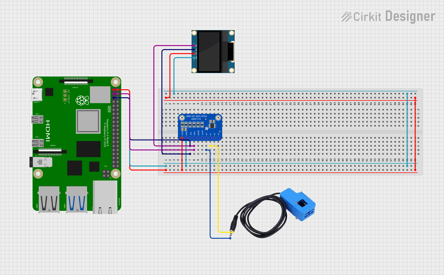 Open Project in Cirkit Designer
Explore Projects Built with Adafruit AD8495
Open Project in Cirkit DesignerOpen Project in Cirkit DesignerOpen Project in Cirkit DesignerOpen Project in Cirkit DesignerCommon Applications and Use Cases
- Industrial temperature monitoring
- HVAC systems
- Scientific experiments requiring precise temperature measurements
- Embedded systems and IoT temperature sensing
- Home automation projects involving temperature control
Technical Specifications
The Adafruit AD8495 is designed to work seamlessly with thermocouples and microcontrollers. Below are its key technical details:
Key Technical Details
| Parameter | Value |
|---|---|
| Supply Voltage (Vcc) | 3.3V to 5V |
| Output Voltage Range | 0V to Vcc |
| Supported Thermocouples | K-type, J-type |
| Temperature Range | -250°C to +1250°C (K-type thermocouple) |
| Amplifier Gain | 122.4 mV/°C (K-type thermocouple) |
| Accuracy | ±2°C (typical) |
| Noise Performance | Low noise design |
| Operating Temperature | -40°C to +125°C |
| Dimensions | 25mm x 20mm x 3mm |
Pin Configuration and Descriptions
The Adafruit AD8495 breakout board has the following pin configuration:
| Pin Name | Description |
|---|---|
| VCC | Power supply input (3.3V to 5V). Connect to the power source of your system. |
| GND | Ground. Connect to the ground of your system. |
| OUT | Analog output. Provides a voltage proportional to the measured temperature. |
| T+ | Positive thermocouple input. Connect to the positive lead of the thermocouple. |
| T- | Negative thermocouple input. Connect to the negative lead of the thermocouple. |
Usage Instructions
The Adafruit AD8495 is straightforward to use in temperature sensing applications. Follow the steps below to integrate it into your circuit:
How to Use the Component in a Circuit
- Power the AD8495: Connect the
VCCpin to a 3.3V or 5V power source and theGNDpin to the ground of your system. - Connect the Thermocouple: Attach the positive lead of the thermocouple to the
T+pin and the negative lead to theT-pin. - Read the Output: The
OUTpin provides an analog voltage proportional to the temperature. This can be read using an analog-to-digital converter (ADC) on a microcontroller, such as an Arduino UNO. - Calculate the Temperature: Use the amplifier's gain (122.4 mV/°C for K-type thermocouples) to convert the output voltage into a temperature reading.
Important Considerations and Best Practices
- Ensure the thermocouple leads are properly connected to the
T+andT-pins. Reversing the leads will result in incorrect readings. - Use a stable power supply to minimize noise and improve accuracy.
- Avoid placing the AD8495 near high-frequency noise sources or heat-generating components.
- If using an Arduino UNO, ensure the
OUTpin is connected to one of the analog input pins (e.g., A0).
Example Arduino Code
Below is an example Arduino sketch to read the temperature from the AD8495:
// Define the analog pin connected to the AD8495 OUT pin
const int analogPin = A0;

// Define the amplifier gain for K-type thermocouples (122.4 mV/°C)
const float gain = 0.1224; // Voltage per degree Celsius

void setup() {
  Serial.begin(9600); // Initialize serial communication
}

void loop() {
  // Read the analog voltage from the AD8495
  int analogValue = analogRead(analogPin);

  // Convert the analog value to voltage (assuming 5V reference)
  float voltage = (analogValue / 1023.0) * 5.0;

  // Calculate the temperature in Celsius
  float temperatureC = voltage / gain;

  // Print the temperature to the Serial Monitor
  Serial.print("Temperature: ");
  Serial.print(temperatureC);
  Serial.println(" °C");

  delay(1000); // Wait 1 second before the next reading
}
Troubleshooting and FAQs
Common Issues and Solutions
No Output Voltage or Incorrect Readings
- Cause: Thermocouple leads are reversed or not connected properly.
- Solution: Verify the connections to the
T+andT-pins. Ensure the positive lead is connected toT+and the negative lead toT-.
Fluctuating or Noisy Readings
- Cause: Power supply instability or external noise interference.
- Solution: Use a decoupling capacitor (e.g., 0.1 µF) between
VCCandGND. Place the AD8495 away from noise sources.
Output Voltage Exceeds Expected Range
- Cause: Thermocouple is exposed to temperatures outside its supported range.
- Solution: Ensure the thermocouple is operating within its specified temperature range.
Arduino Reads Incorrect Temperature
- Cause: Incorrect reference voltage or gain value in the code.
- Solution: Verify the Arduino's reference voltage and ensure the correct gain value (122.4 mV/°C for K-type) is used in calculations.
FAQs
Q: Can I use the AD8495 with thermocouples other than K-type?
A: Yes, the AD8495 also supports J-type thermocouples. However, the gain value will differ. Refer to the datasheet for the specific gain value for J-type thermocouples.
Q: What is the maximum temperature the AD8495 can measure?
A: The AD8495 can measure up to +1250°C with a K-type thermocouple. However, ensure the thermocouple itself supports this range.
Q: Can I use the AD8495 with a 3.3V microcontroller?
A: Yes, the AD8495 operates with a supply voltage of 3.3V to 5V, making it compatible with 3.3V microcontrollers like the ESP32 or Raspberry Pi Pico.
Q: How do I improve measurement accuracy?
A: Use a high-quality thermocouple, minimize noise in the circuit, and ensure proper calibration of your system.
This concludes the documentation for the Adafruit AD8495. For further details, refer to the official datasheet or Adafruit's product page.