
How to Use RTC DS1307: Examples, Pinouts, and Specs
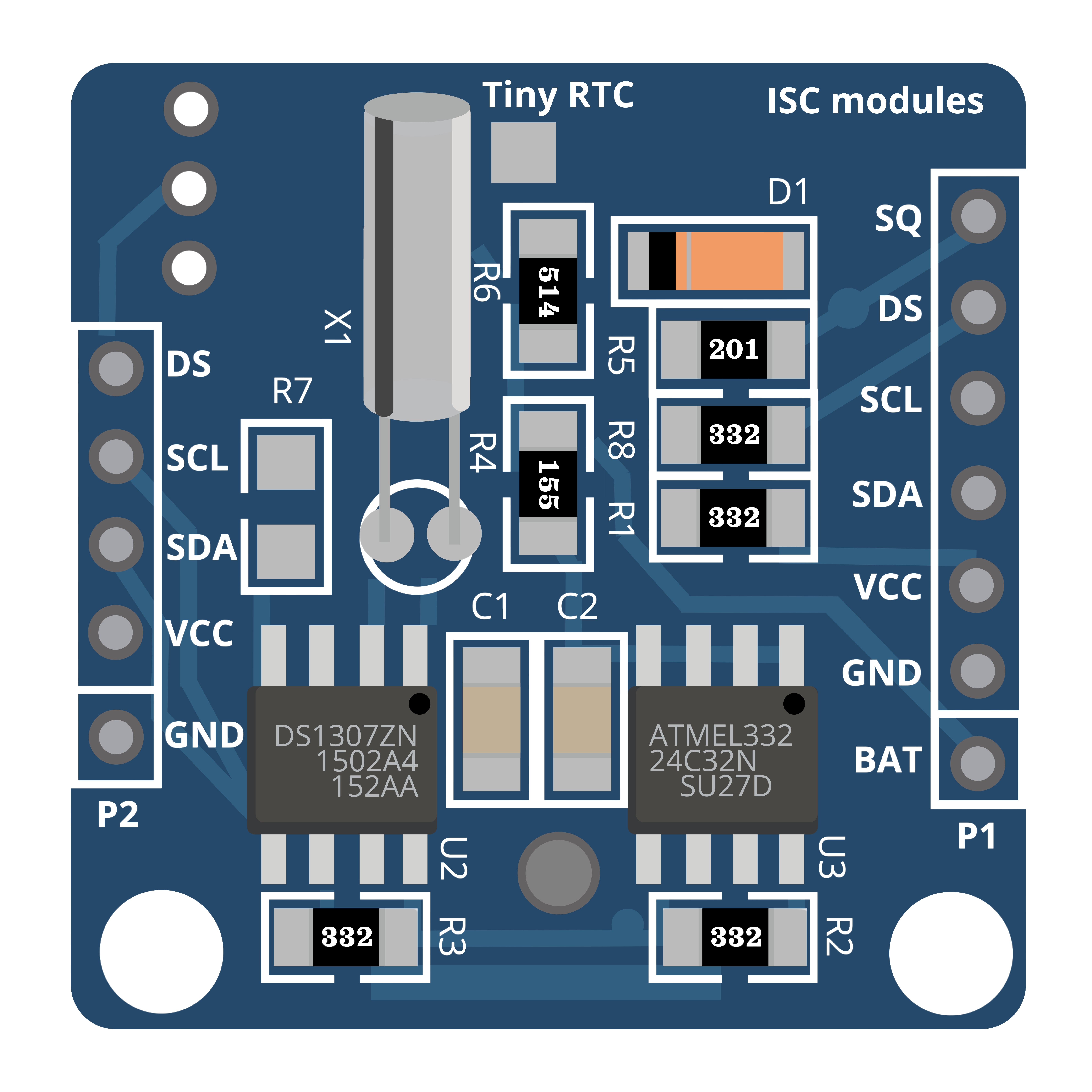
 Design with RTC DS1307 in Cirkit Designer
Introduction
The Real-Time Clock (RTC) DS1307 is a low-power, full binary-coded decimal (BCD) clock/calendar with 56 bytes of NV SRAM. It provides precise timekeeping with a built-in 32.768 kHz crystal oscillator. The DS1307 communicates with microcontrollers via an I2C interface. Common applications include timekeeping in embedded systems, data loggers, clocks, and other devices that require an accurate time base.
Explore Projects Built with RTC DS1307
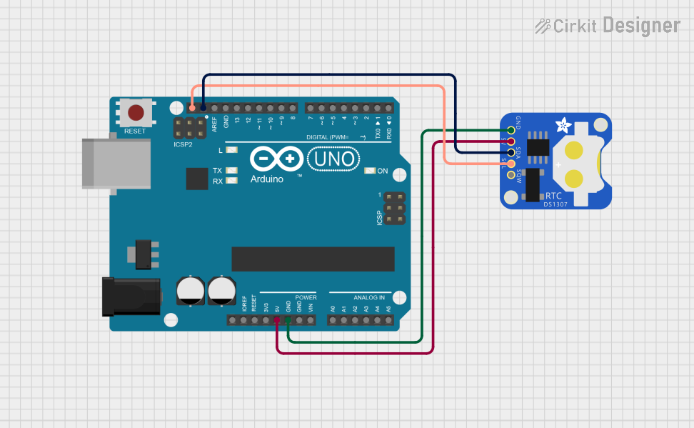
 Open Project in Cirkit Designer
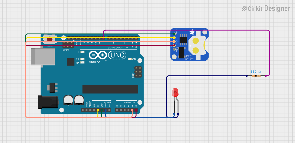
 Open Project in Cirkit Designer
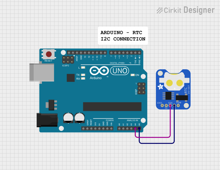
 Open Project in Cirkit Designer
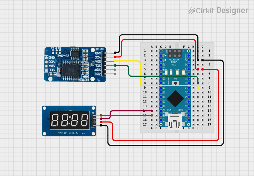
 Open Project in Cirkit Designer
Explore Projects Built with RTC DS1307

 Open Project in Cirkit Designer
 Open Project in Cirkit Designer
 Open Project in Cirkit Designer
 Open Project in Cirkit Designer
Technical Specifications
Key Technical Details
- Voltage Supply: 4.5V to 5.5V
- Current: 500nA at 5V (Battery-Backup Mode)
- Timekeeping Current: 200µA at 5V
- Operating Temperature: 0°C to +70°C
- Frequency Output: 32.768 kHz
- Memory: 56-byte battery-backed NV SRAM
- Interface: I2C Serial
- Address: 0x68 (7-bit I2C address)
Pin Configuration and Descriptions
| Pin Number | Name | Description |
|---|---|---|
| 1 | GND | Ground pin, connected to the system ground |
| 2 | Vbat | Battery input for any standard 3V lithium cell or other energy source |
| 3 | Vcc | Main power supply; should be between 4.5V and 5.5V |
| 4 | SDA | Serial Data Line for I2C communication |
| 5 | SCL | Serial Clock Line for I2C communication |
| 6 | SQW/OUT | Square Wave/Output Driver (configurable) |
| 7 | X1 | Input to the 32.768 kHz crystal oscillator |
| 8 | X2 | Output from the 32.768 kHz crystal oscillator |
Usage Instructions
Integration with a Circuit
- Connect the Vcc pin to a 5V power supply.
- Connect the GND pin to the ground of the power supply.
- Connect the SDA and SCL pins to the corresponding I2C data and clock lines on your microcontroller.
- Optionally, connect the SQW/OUT pin if a square wave output is required.
- Attach a 3V lithium cell to the Vbat pin to ensure timekeeping during power interruptions.
Best Practices
- Place a 0.1µF bypass capacitor near the Vcc pin to filter out noise.
- Use pull-up resistors on the SDA and SCL lines, typically 4.7kΩ.
- Ensure that the battery used for Vbat is capable of providing the necessary voltage for the duration of the intended backup period.
- Avoid placing the crystal and DS1307 near high-temperature components to prevent timekeeping inaccuracies.
Example Code for Arduino UNO
#include <Wire.h>
#include <RTClib.h>

RTC_DS1307 rtc;

void setup() {
  Serial.begin(9600);
  if (!rtc.begin()) {
    Serial.println("Couldn't find RTC");
    while (1);
  }

  if (!rtc.isrunning()) {
    Serial.println("RTC is NOT running!");
    // Following line sets the RTC to the date & time this sketch was compiled
    rtc.adjust(DateTime(F(__DATE__), F(__TIME__)));
  }
}

void loop() {
  DateTime now = rtc.now();

  Serial.print(now.year(), DEC);
  Serial.print('/');
  Serial.print(now.month(), DEC);
  Serial.print('/');
  Serial.print(now.day(), DEC);
  Serial.print(" ");
  Serial.print(now.hour(), DEC);
  Serial.print(':');
  Serial.print(now.minute(), DEC);
  Serial.print(':');
  Serial.print(now.second(), DEC);
  Serial.println();

  delay(1000);
}
Troubleshooting and FAQs
Common Issues
- Time not accurate: Ensure the crystal is properly seated and not subject to temperature fluctuations.
- I2C communication failure: Check pull-up resistors on SDA and SCL lines and verify connections.
- RTC not found: Confirm that the RTC is powered and that the I2C address is correct.
Solutions and Tips
- If the time drifts, consider calibrating the load capacitance for the crystal.
- For battery backup issues, verify the battery voltage and replace if necessary.
- Use the
rtc.adjust()function sparingly to avoid wearing out the RTC's internal oscillator calibration.
FAQs
Q: Can the DS1307 be used in a 3.3V system? A: The DS1307 is designed for 5V systems, but it can work at 3.3V with proper level shifting for I2C lines.
Q: How long will the RTC keep time on battery backup? A: This depends on the battery capacity and the quality of the crystal. Typically, it can last for several years.
Q: Is it necessary to use an external crystal with the DS1307? A: Yes, the DS1307 requires an external 32.768 kHz crystal to function properly.
Q: Can the DS1307 be used to generate interrupt signals? A: Yes, the SQW/OUT pin can be configured to output a square wave signal which can be used as an interrupt source.