How to Use IndusBoard: Examples, Pinouts, and Specs
Introduction
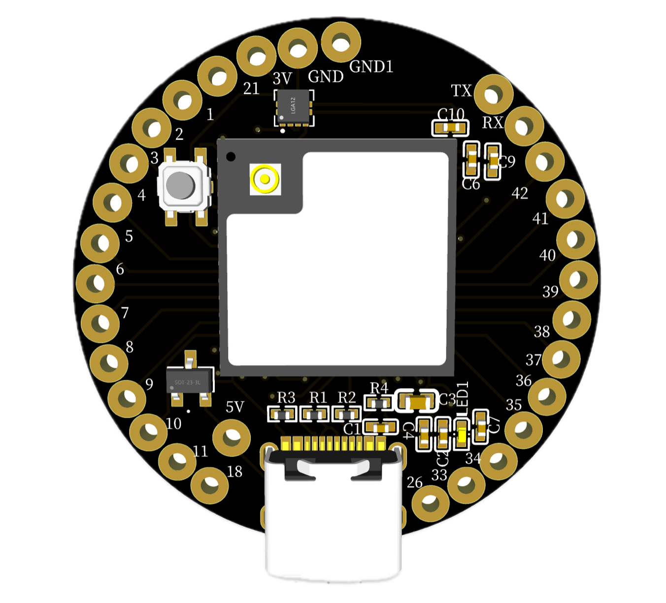
The IndusBoard Coin V2 is a versatile development board designed for industrial applications. It features multiple I/O options, robust power management, and compatibility with various communication protocols. This board is ideal for developing and prototyping industrial automation systems, IoT devices, and other embedded applications.
Common Applications:
- Industrial automation
- IoT (Internet of Things) devices
- Embedded systems development
- Prototyping and testing of industrial equipment
Explore Projects Built with IndusBoard

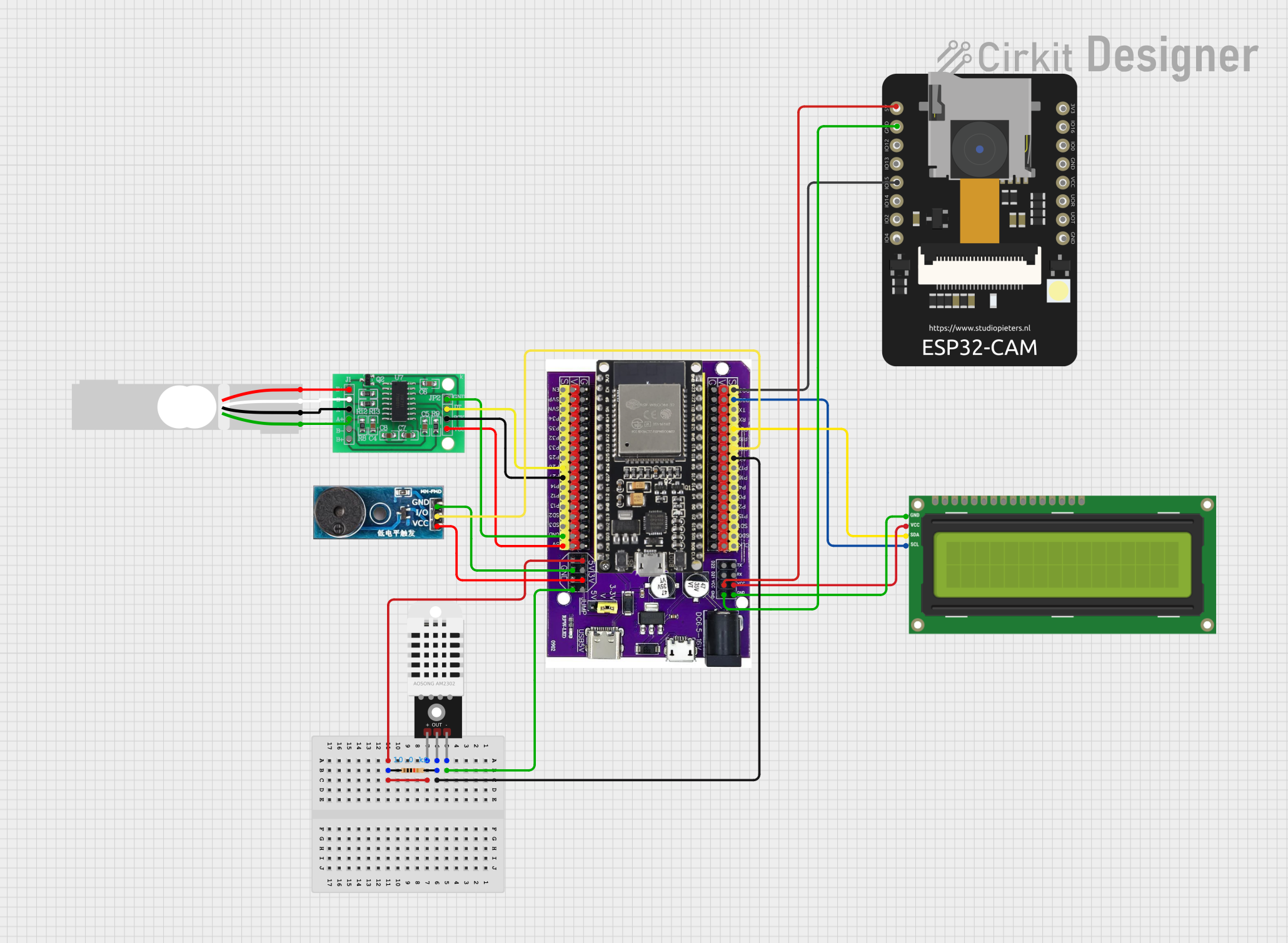

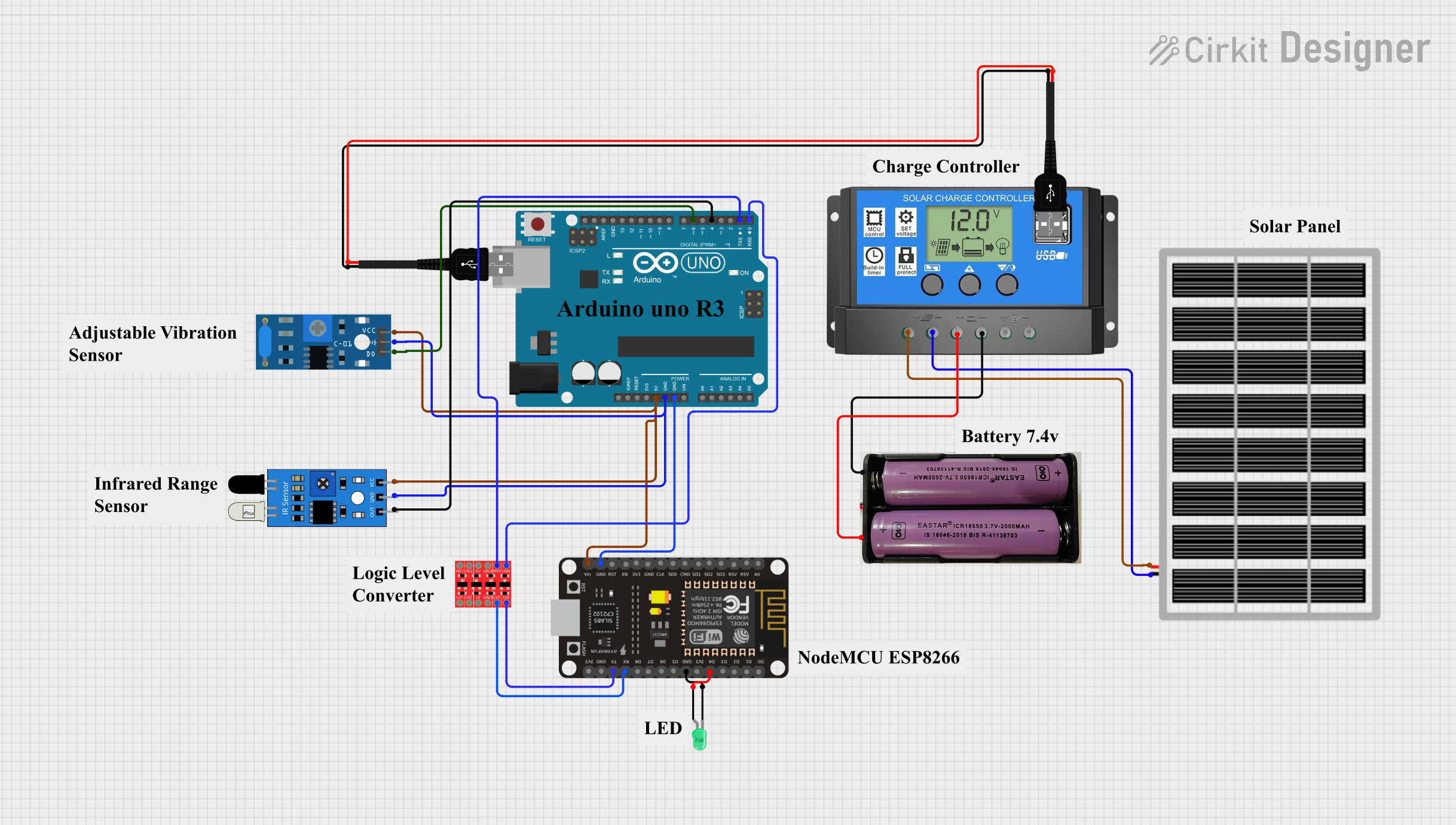
Explore Projects Built with IndusBoard
Technical Specifications
Key Technical Details
| Parameter | Value |
|---|---|
| Operating Voltage | 3.3V / 5V |
| Input Voltage (recommended) | 7-12V |
| Input Voltage (limit) | 6-20V |
| Digital I/O Pins | 14 (of which 6 provide PWM output) |
| Analog Input Pins | 6 |
| DC Current per I/O Pin | 20 mA |
| Flash Memory | 32 KB (ATmega328P) |
| SRAM | 2 KB (ATmega328P) |
| EEPROM | 1 KB (ATmega328P) |
| Clock Speed | 16 MHz |
Pin Configuration and Descriptions
| Pin Number | Pin Name | Description |
|---|---|---|
| 1 | D0/RX | Digital I/O, UART Receive |
| 2 | D1/TX | Digital I/O, UART Transmit |
| 3 | D2 | Digital I/O |
| 4 | D3 | Digital I/O, PWM |
| 5 | D4 | Digital I/O |
| 6 | D5 | Digital I/O, PWM |
| 7 | D6 | Digital I/O, PWM |
| 8 | D7 | Digital I/O |
| 9 | D8 | Digital I/O |
| 10 | D9 | Digital I/O, PWM |
| 11 | D10 | Digital I/O, PWM |
| 12 | D11 | Digital I/O, PWM |
| 13 | D12 | Digital I/O |
| 14 | D13 | Digital I/O, LED |
| 15 | A0 | Analog Input |
| 16 | A1 | Analog Input |
| 17 | A2 | Analog Input |
| 18 | A3 | Analog Input |
| 19 | A4 | Analog Input, I2C SDA |
| 20 | A5 | Analog Input, I2C SCL |
| 21 | GND | Ground |
| 22 | 5V | 5V Power Output |
| 23 | 3.3V | 3.3V Power Output |
| 24 | VIN | Input Voltage |
| 25 | RESET | Reset |
Usage Instructions
How to Use the Component in a Circuit
Powering the Board:
- Connect the VIN pin to a power source (7-12V recommended).
- Alternatively, you can power the board via the USB port.
Connecting I/O Devices:
- Digital I/O: Connect your digital sensors or actuators to the digital pins (D0-D13).
- Analog Input: Connect your analog sensors to the analog input pins (A0-A5).
Communication:
- UART: Use pins D0 (RX) and D1 (TX) for serial communication.
- I2C: Use pins A4 (SDA) and A5 (SCL) for I2C communication.
Important Considerations and Best Practices
- Ensure that the input voltage does not exceed the recommended limits to avoid damaging the board.
- Use appropriate pull-up or pull-down resistors for digital inputs to ensure stable readings.
- When using PWM outputs, be mindful of the current limits to prevent overheating.
- For reliable communication, use proper shielding and grounding techniques, especially in industrial environments.
Troubleshooting and FAQs
Common Issues and Solutions
Board Not Powering On:
- Solution: Check the power connections and ensure the input voltage is within the recommended range.
Digital I/O Not Responding:
- Solution: Verify the connections and ensure the correct pin numbers are used in the code. Check for proper pull-up or pull-down resistors.
Analog Readings Are Inaccurate:
- Solution: Ensure the analog sensors are properly connected and calibrated. Check for electrical noise and use proper shielding.
Communication Issues (UART/I2C):
- Solution: Verify the wiring and ensure the correct baud rate (for UART) or address (for I2C) is used. Check for proper grounding and shielding.
FAQs
Q1: Can I use the IndusBoard Coin V2 with an Arduino UNO? A1: Yes, the IndusBoard Coin V2 is compatible with the Arduino UNO. You can use the Arduino IDE to program the board.
Q2: What is the maximum current that can be drawn from the 5V and 3.3V pins? A2: The maximum current that can be drawn from the 5V pin is 500 mA, and from the 3.3V pin is 50 mA.
Q3: How do I reset the board? A3: You can reset the board by pressing the RESET button or by connecting the RESET pin to GND momentarily.
Example Code for Arduino UNO
// Example code to blink an LED connected to pin 13

void setup() {
  // Initialize digital pin 13 as an output.
  pinMode(13, OUTPUT);
}

void loop() {
  // Turn the LED on (HIGH is the voltage level)
  digitalWrite(13, HIGH);
  // Wait for a second
  delay(1000);
  // Turn the LED off by making the voltage LOW
  digitalWrite(13, LOW);
  // Wait for a second
  delay(1000);
}
For more information, visit the manufacturer's website.
This documentation provides a comprehensive overview of the IndusBoard Coin V2, including its technical specifications, usage instructions, and troubleshooting tips. Whether you are a beginner or an experienced user, this guide will help you make the most of this versatile development board.