How to Use Adafruit PiUART: Examples, Pinouts, and Specs
Introduction
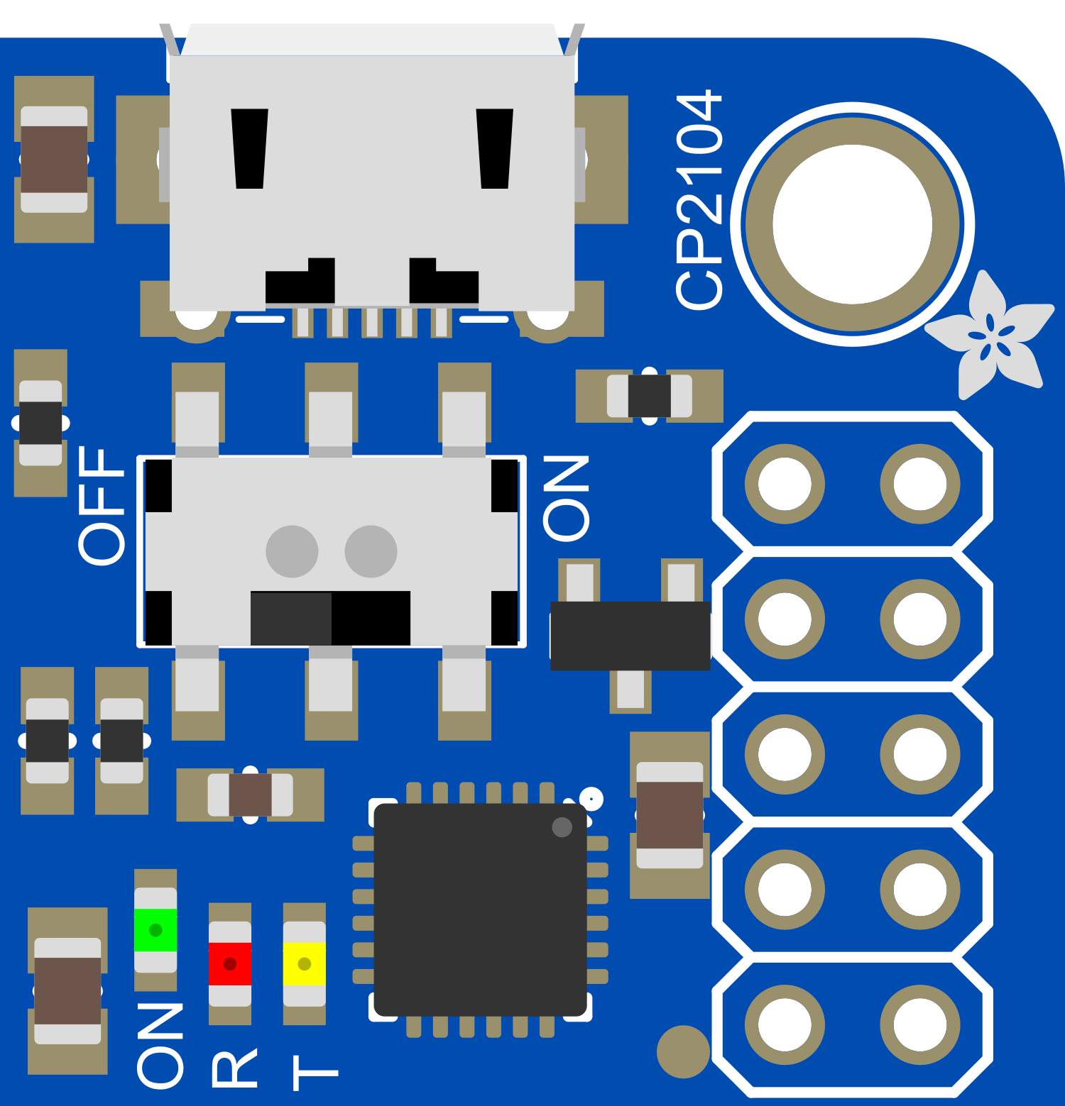
The Adafruit PiUART is a UART (Universal Asynchronous Receiver/Transmitter) interface board specifically designed for use with the Raspberry Pi series of single-board computers. This component simplifies the process of connecting UART-compatible devices, such as serial consoles, to the Raspberry Pi's GPIO (General Purpose Input/Output) pins. It is an essential tool for developers and hobbyists who need to establish serial communication between their Raspberry Pi and other hardware components.
Explore Projects Built with Adafruit PiUART
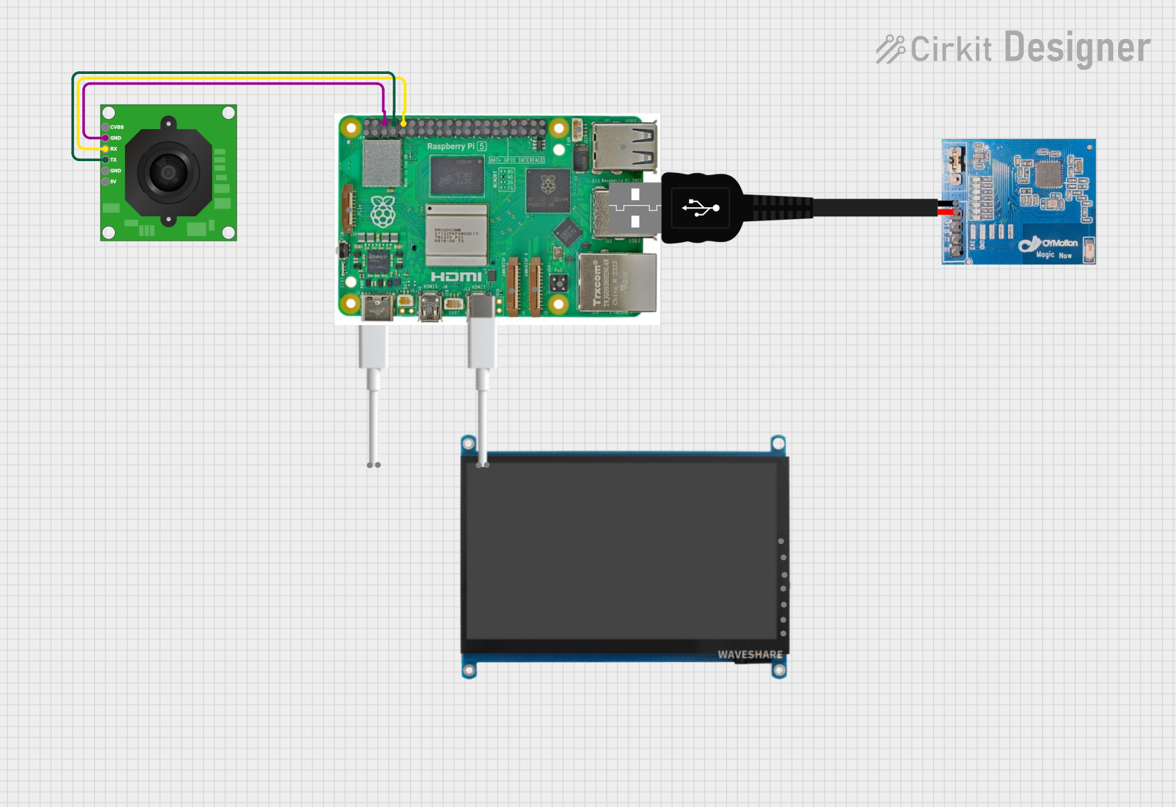
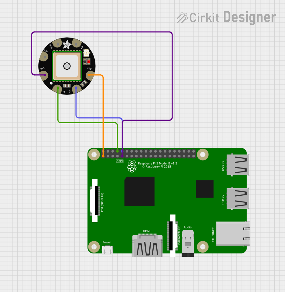

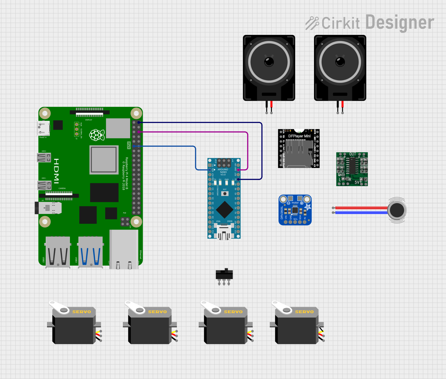
Explore Projects Built with Adafruit PiUART
Common Applications and Use Cases
- Serial console for Raspberry Pi debugging and configuration
- Interfacing with GPS modules, RFID readers, and other serial devices
- Data logging from sensors with UART output
- Robotics and embedded systems projects requiring serial communication
Technical Specifications
Key Technical Details
- Operating Voltage: 3.3V (matches Raspberry Pi logic levels)
- Baud Rate: Configurable, supports standard baud rates (e.g., 9600, 115200)
- Connectivity: Direct connection to Raspberry Pi GPIO header
Pin Configuration and Descriptions
| Pin Number | Name | Description |
|---|---|---|
| 1 | VCC | 3.3V Power Supply Input |
| 2 | TX | Transmit Data (PiUART to Raspberry Pi) |
| 3 | RX | Receive Data (Raspberry Pi to PiUART) |
| 4 | GND | Ground Connection |
Usage Instructions
How to Use the Component in a Circuit
- Power Connection: Connect the VCC pin of the PiUART to a 3.3V pin on the Raspberry Pi GPIO header.
- Ground Connection: Connect the GND pin of the PiUART to a ground pin on the Raspberry Pi GPIO header.
- Data Connection: Connect the TX pin of the PiUART to the RX pin on the Raspberry Pi, and the RX pin of the PiUART to the TX pin on the Raspberry Pi.
Important Considerations and Best Practices
- Ensure that the Raspberry Pi is powered off before connecting the PiUART to prevent any electrical damage.
- Use a logic level converter if you need to connect the PiUART to devices that operate at different logic levels (e.g., 5V).
- Always double-check connections before powering up the Raspberry Pi to avoid short circuits.
- For reliable communication, configure both the Raspberry Pi and the connected UART device to use the same baud rate.
Troubleshooting and FAQs
Common Issues Users Might Face
- No Communication: Ensure that the TX and RX pins are not reversed and that the correct baud rate is set.
- Garbled Data: Check for loose connections and verify that both devices are using the same baud rate and data format.
- Power Issues: Confirm that the PiUART is receiving 3.3V power from the Raspberry Pi.
Solutions and Tips for Troubleshooting
- If you encounter issues with serial communication, try using a different baud rate or checking the serial port settings on the Raspberry Pi.
- Use a multimeter to verify that the PiUART is receiving the correct voltage.
- Consult the Raspberry Pi's documentation for the correct GPIO pinout and ensure that you are using the correct pins for UART communication.
FAQs
Q: Can I use the PiUART with a 5V logic device? A: No, the PiUART is designed for 3.3V logic levels. Use a logic level converter for 5V devices.
Q: How do I change the baud rate on the PiUART? A: The baud rate is set within your Raspberry Pi's software configuration. Refer to the Raspberry Pi's serial interface configuration settings to adjust the baud rate.
Q: Is the PiUART compatible with all Raspberry Pi models? A: The PiUART is compatible with any Raspberry Pi model that has a GPIO header with UART pins available.
Example Code for Raspberry Pi
Below is an example Python script for sending a simple message through the PiUART to a connected serial device. This script assumes you have already configured the serial port on your Raspberry Pi.
import serial
import time
Initialize serial connection on the Raspberry Pi
ser = serial.Serial( port='/dev/serial0', # Replace with the correct serial port if necessary baudrate=9600, # Set the baud rate to match the connected device timeout=1 )
Function to send a message through the PiUART
def send_message(message): ser.write(message.encode())
Main loop to send messages periodically
try: while True: send_message("Hello from Raspberry Pi!") time.sleep(2) # Wait for 2 seconds before sending the next message except KeyboardInterrupt: ser.close() # Close the serial connection when the script is stopped
Remember to configure the serial port on your Raspberry Pi and install the `pyserial` package before running the script. Use the command `pip install pyserial` to install the package if it's not already installed.