How to Use GX16 NAMED PIN: Examples, Pinouts, and Specs
Introduction
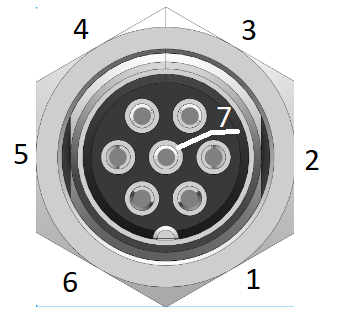
The GX16 named pin is a circular electrical connector widely used in aviation, industrial equipment, and other electronic applications. It features a robust design with multiple pins, allowing for secure and reliable connections for both power and signal lines. Its durable construction and ease of use make it a popular choice for connecting components in harsh environments or where frequent disconnections are required.
Explore Projects Built with GX16 NAMED PIN


Explore Projects Built with GX16 NAMED PIN
Common Applications:
- Aviation systems for power and signal connections
- Industrial machinery and automation equipment
- Audio and video equipment
- Robotics and DIY electronics projects
- Power supply connections in electronic devices
Technical Specifications
Key Technical Details:
- Connector Type: Circular, threaded locking mechanism
- Pin Count: Typically 2 to 8 pins (depending on the model)
- Rated Voltage: 125V to 250V (varies by model)
- Rated Current: 5A to 10A (varies by model)
- Material: Metal shell with nickel plating for durability
- Operating Temperature: -20°C to +85°C
- Mounting Style: Panel mount or cable mount
- Contact Resistance: ≤ 5mΩ
- Insulation Resistance: ≥ 1000MΩ at 500V DC
Pin Configuration and Descriptions:
The pin configuration varies depending on the number of pins in the GX16 connector. Below is an example for a 4-pin GX16 connector:
| Pin Number | Description | Typical Use |
|---|---|---|
| 1 | Power Supply Positive | Connect to VCC or +ve line |
| 2 | Power Supply Negative | Connect to GND or -ve line |
| 3 | Signal Line 1 | Data or control signal |
| 4 | Signal Line 2 | Data or control signal |
For other pin configurations (e.g., 2-pin, 5-pin, 8-pin), refer to the specific datasheet of the GX16 model being used.
Usage Instructions
How to Use the GX16 Named Pin in a Circuit:
- Identify the Pinout: Refer to the pin configuration table or datasheet to identify the function of each pin.
- Prepare the Wires: Strip the insulation from the wires you intend to connect to the GX16 connector.
- Solder the Wires: Solder the wires to the corresponding pins on the connector. Ensure proper insulation to avoid short circuits.
- Secure the Connection: If using a cable-mounted connector, tighten the threaded locking mechanism to secure the connection.
- Panel Mounting (if applicable): For panel-mounted connectors, drill a hole in the panel, insert the connector, and secure it with the provided nut.
Important Considerations:
- Ensure the voltage and current ratings of the GX16 connector match your application.
- Avoid over-tightening the threaded locking mechanism to prevent damage.
- Use heat shrink tubing or insulation tape to protect soldered connections.
- Verify the pinout before connecting to avoid reversing polarity or miswiring.
Example: Connecting a GX16 to an Arduino UNO
If using a GX16 connector to transmit signals to an Arduino UNO, follow these steps:
- Connect the signal pins of the GX16 connector to the appropriate digital or analog pins on the Arduino.
- Connect the power supply pins of the GX16 to the Arduino's 5V and GND pins.
- Use the following sample code to read data from the GX16 signal pins:
// Example code for reading data from a GX16 connector
const int signalPin1 = 2; // Connect GX16 Signal Line 1 to Arduino Pin 2
const int signalPin2 = 3; // Connect GX16 Signal Line 2 to Arduino Pin 3

void setup() {
  pinMode(signalPin1, INPUT); // Set Signal Line 1 as input
  pinMode(signalPin2, INPUT); // Set Signal Line 2 as input
  Serial.begin(9600); // Initialize serial communication
}

void loop() {
  int signal1 = digitalRead(signalPin1); // Read data from Signal Line 1
  int signal2 = digitalRead(signalPin2); // Read data from Signal Line 2

  // Print the signal values to the Serial Monitor
  Serial.print("Signal 1: ");
  Serial.println(signal1);
  Serial.print("Signal 2: ");
  Serial.println(signal2);

  delay(500); // Wait for 500ms before reading again
}
Troubleshooting and FAQs
Common Issues:
Loose Connections:
- Cause: Improper tightening of the threaded locking mechanism.
- Solution: Ensure the connector is securely fastened.
Incorrect Pinout:
- Cause: Misidentification of pin functions.
- Solution: Double-check the pin configuration using the datasheet.
Signal Interference:
- Cause: Poor insulation or proximity to high-power lines.
- Solution: Use shielded cables and maintain proper separation from power lines.
Overheating:
- Cause: Exceeding the rated current or voltage.
- Solution: Verify that the connector's ratings match your application.
FAQs:
Q1: Can I use a GX16 connector for high-frequency signals?
A1: Yes, but ensure the cable and connector are shielded to minimize signal loss or interference.
Q2: How do I clean a GX16 connector?
A2: Use a soft brush or compressed air to remove dust. Avoid using water or harsh chemicals.
Q3: Can I use a GX16 connector outdoors?
A3: While the metal shell provides some protection, it is not fully waterproof. Use additional sealing or a weatherproof version for outdoor applications.
Q4: What tools are needed to assemble a GX16 connector?
A4: You will need a soldering iron, wire stripper, and possibly a wrench for tightening the locking nut.
By following this documentation, you can effectively use the GX16 named pin connector in your projects and troubleshoot common issues with ease.