Cirkit Designer Logo
Cirkit Designer
Your all-in-one circuit design IDE
Home / 
Component Documentation

How to Use BDC PWM DC MOTOR CONTROLLER 10A 6-90V: Examples, Pinouts, and Specs

Image of BDC PWM DC MOTOR CONTROLLER 10A 6-90V
Cirkit Designer LogoDesign with BDC PWM DC MOTOR CONTROLLER 10A 6-90V in Cirkit Designer

Introduction

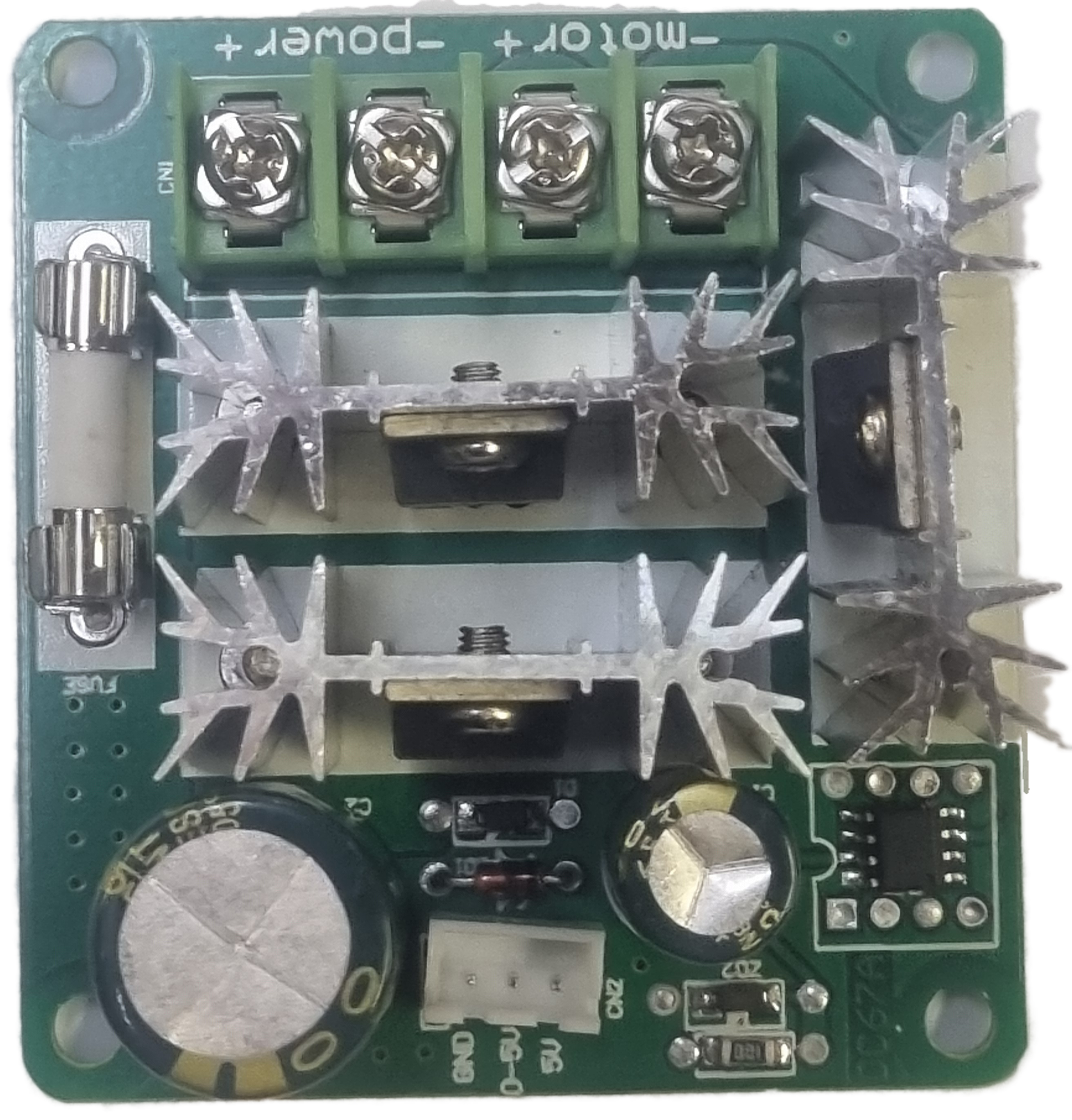
The BDD PWM DC Motor Controller 10A 6-90V is an electronic device designed to control the speed of a DC motor using Pulse Width Modulation (PWM). It is capable of handling currents up to 10A and can be used with a supply voltage ranging from 6V to 90V. This controller is commonly used in applications such as robotics, automotive, industrial control systems, and DIY projects where precise motor speed control is required.

Explore Projects Built with BDC PWM DC MOTOR CONTROLLER 10A 6-90V

Use Cirkit Designer to design, explore, and prototype these projects online. Some projects support real-time simulation. Click "Open Project" to start designing instantly!
12V PWM-Controlled Water Pump System
Image of moter speed controller: A project utilizing BDC PWM DC MOTOR CONTROLLER 10A 6-90V in a practical application
This circuit is designed to control the speed of a water pump using a PWM DC motor speed controller. The 12V5Ah battery provides power to the speed controller, which in turn regulates the power supplied to the water pump, allowing for adjustable flow rates. There is no microcontroller code provided, indicating that the speed control is likely adjusted manually via the PWM controller.
Cirkit Designer LogoOpen Project in Cirkit Designer
Dual DC Motor Control Circuit with Speed Regulation and Indicator Lamp
Image of egg peeling machine: A project utilizing BDC PWM DC MOTOR CONTROLLER 10A 6-90V in a practical application
This circuit includes a 12V 200Ah battery that powers a water pump and two DC motors, each controlled by a separate 12v~40v 10A PWM DC motor speed controller. A rocker switch (SPST) is used to control the power flow to the water pump and a pilot lamp indicates when the pump is powered. The DC motors' speed can be adjusted by the PWM controllers, and wire connectors are used to organize the connections between components.
Cirkit Designer LogoOpen Project in Cirkit Designer
PWM-Controlled DC Motor Speed Regulator with DC Barrel Jack Power Input
Image of Siren: A project utilizing BDC PWM DC MOTOR CONTROLLER 10A 6-90V in a practical application
This circuit controls the speed of a DC motor using a 12V PWM speed controller. Power is supplied to the speed controller through a 2.1mm DC barrel jack, which then modulates the voltage and current to the motor's terminals to adjust its speed. There is no microcontroller code involved, indicating that the speed control is likely adjusted manually via the speed controller's onboard settings.
Cirkit Designer LogoOpen Project in Cirkit Designer
Battery-Powered DC Motor Control System with Speed Regulation
Image of wheel chair: A project utilizing BDC PWM DC MOTOR CONTROLLER 10A 6-90V in a practical application
This circuit is a motor control system powered by two 12V batteries connected in series, with a 3-position switch to control a PWM motor speed controller. The system includes a pilot lamp for status indication and a NI-MH battery charger powered by an AC source.
Cirkit Designer LogoOpen Project in Cirkit Designer

Explore Projects Built with BDC PWM DC MOTOR CONTROLLER 10A 6-90V

Use Cirkit Designer to design, explore, and prototype these projects online. Some projects support real-time simulation. Click "Open Project" to start designing instantly!
Image of moter speed controller: A project utilizing BDC PWM DC MOTOR CONTROLLER 10A 6-90V in a practical application
12V PWM-Controlled Water Pump System
This circuit is designed to control the speed of a water pump using a PWM DC motor speed controller. The 12V5Ah battery provides power to the speed controller, which in turn regulates the power supplied to the water pump, allowing for adjustable flow rates. There is no microcontroller code provided, indicating that the speed control is likely adjusted manually via the PWM controller.
Cirkit Designer LogoOpen Project in Cirkit Designer
Image of egg peeling machine: A project utilizing BDC PWM DC MOTOR CONTROLLER 10A 6-90V in a practical application
Dual DC Motor Control Circuit with Speed Regulation and Indicator Lamp
This circuit includes a 12V 200Ah battery that powers a water pump and two DC motors, each controlled by a separate 12v~40v 10A PWM DC motor speed controller. A rocker switch (SPST) is used to control the power flow to the water pump and a pilot lamp indicates when the pump is powered. The DC motors' speed can be adjusted by the PWM controllers, and wire connectors are used to organize the connections between components.
Cirkit Designer LogoOpen Project in Cirkit Designer
Image of Siren: A project utilizing BDC PWM DC MOTOR CONTROLLER 10A 6-90V in a practical application
PWM-Controlled DC Motor Speed Regulator with DC Barrel Jack Power Input
This circuit controls the speed of a DC motor using a 12V PWM speed controller. Power is supplied to the speed controller through a 2.1mm DC barrel jack, which then modulates the voltage and current to the motor's terminals to adjust its speed. There is no microcontroller code involved, indicating that the speed control is likely adjusted manually via the speed controller's onboard settings.
Cirkit Designer LogoOpen Project in Cirkit Designer
Image of wheel chair: A project utilizing BDC PWM DC MOTOR CONTROLLER 10A 6-90V in a practical application
Battery-Powered DC Motor Control System with Speed Regulation
This circuit is a motor control system powered by two 12V batteries connected in series, with a 3-position switch to control a PWM motor speed controller. The system includes a pilot lamp for status indication and a NI-MH battery charger powered by an AC source.
Cirkit Designer LogoOpen Project in Cirkit Designer

Technical Specifications

Key Technical Details

  • Supply Voltage (Vcc): 6V to 90V DC
  • Output Current (Continuous): Up to 10A
  • PWM Frequency: Adjustable, typically around 15kHz
  • Duty Cycle Range: 0% to 100%
  • Control Method: PWM
  • Operating Temperature: -20°C to 40°C

Pin Configuration and Descriptions

Pin Number Pin Name Description
1 V+ Positive supply voltage input (6V to 90V DC)
2 GND Ground connection
3 OUT+ Positive motor output
4 OUT- Negative motor output
5 VR Speed control potentiometer (if applicable)
6 SW On/Off switch (if applicable)

Usage Instructions

How to Use the Component in a Circuit

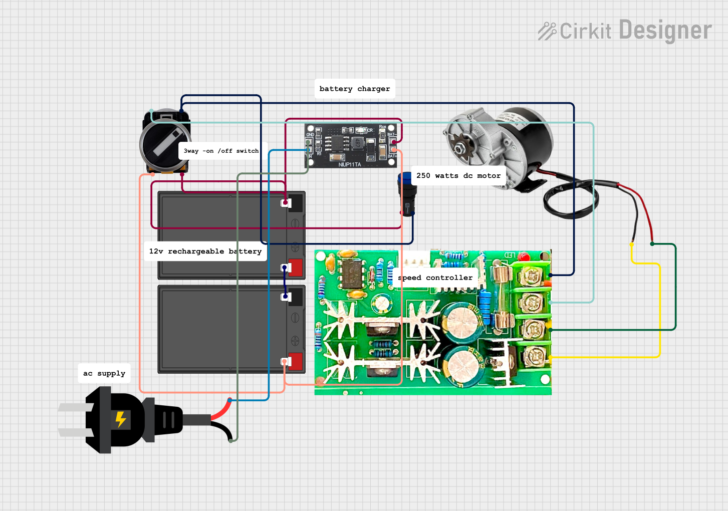
  1. Power Supply Connection: Connect the positive terminal of your DC power supply to the V+ pin and the negative terminal to the GND pin.
  2. Motor Connection: Connect the positive terminal of the DC motor to the OUT+ pin and the negative terminal to the OUT- pin.
  3. Speed Control: If your controller has a built-in potentiometer (VR), you can adjust the motor speed by turning the knob. For controllers without a potentiometer, an external PWM signal can be used to control the speed.
  4. Switching On/Off: If your controller has a built-in switch (SW), use it to turn the motor on or off. Otherwise, you can use an external switch or relay.

Important Considerations and Best Practices

  • Ensure that the power supply voltage and motor specifications do not exceed the controller's ratings.
  • Always start with a low speed setting and gradually increase to prevent damage to the motor.
  • Use appropriate heat sinks if operating near the maximum current rating to prevent overheating.
  • Keep the controller away from moisture and dust.
  • When using with an Arduino or similar microcontroller, ensure that the PWM signal levels are compatible.

Example Code for Arduino UNO

// Example code to control a BDD PWM DC Motor Controller with an Arduino UNO

const int pwmPin = 3; // Connect to the PWM input of the motor controller

void setup() {
  pinMode(pwmPin, OUTPUT);
}

void loop() {
  // Set motor speed to 50% duty cycle
  analogWrite(pwmPin, 127); // 127 is approximately 50% of 255

  delay(2000); // Run at this speed for 2 seconds

  // Stop the motor
  analogWrite(pwmPin, 0);

  delay(1000); // Motor is stopped for 1 second

  // Increase speed to 75% duty cycle
  analogWrite(pwmPin, 191); // 191 is approximately 75% of 255

  delay(2000); // Run at this speed for 2 seconds

  // Stop the motor
  analogWrite(pwmPin, 0);

  delay(1000); // Motor is stopped for 1 second
}

Troubleshooting and FAQs

Common Issues

  • Motor not responding: Check connections and ensure the power supply is within the specified range.
  • Motor overheating: Reduce the load or duty cycle, and ensure proper ventilation.
  • Inconsistent motor speed: Verify that the PWM signal is stable and within the correct frequency range.

Solutions and Tips for Troubleshooting

  • Double-check wiring and connections for any loose contacts.
  • Measure the supply voltage to ensure it falls within the specified range.
  • If using an external PWM signal, use an oscilloscope to verify the signal's integrity.
  • Ensure that the motor's current draw does not exceed 10A.

FAQs

Q: Can I control the motor speed using a microcontroller? A: Yes, you can use a microcontroller like an Arduino to generate a PWM signal and control the motor speed.

Q: What is the maximum frequency for the PWM input? A: The maximum frequency typically is around 15kHz, but it's best to consult the specific controller's datasheet for precise values.

Q: Can this controller be used for motors requiring more than 10A? A: No, this controller is rated for a maximum continuous current of 10A. Using it with motors that require more current can damage the controller.