How to Use Laser Sensor: Examples, Pinouts, and Specs
Introduction
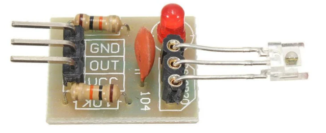
The OTC OT3660 Laser Sensor is a precision device that utilizes laser technology to detect the distance or presence of objects. It operates by emitting a laser beam and measuring the time it takes for the beam to reflect back from the target object. This time-of-flight (ToF) measurement enables accurate distance calculations, making the OT3660 ideal for a wide range of applications.
Explore Projects Built with Laser Sensor
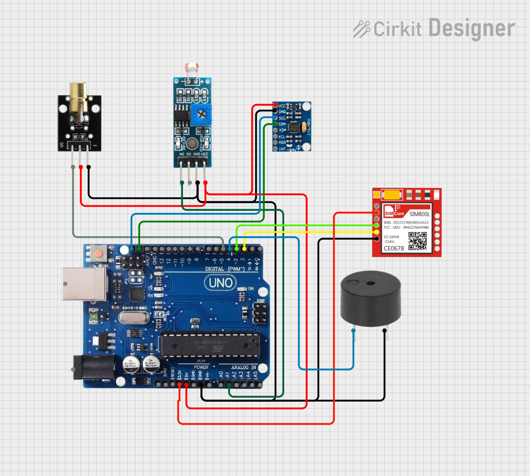
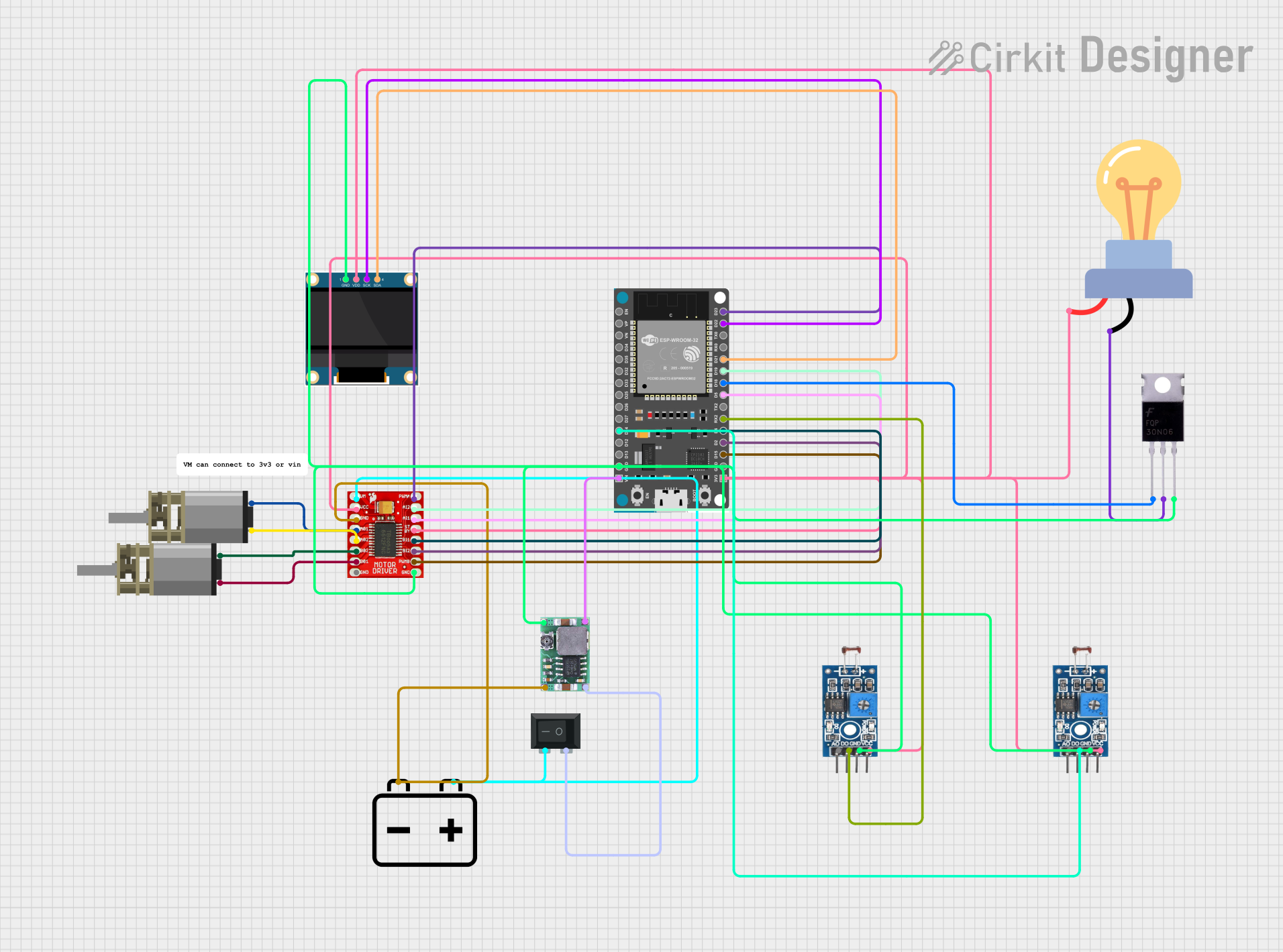
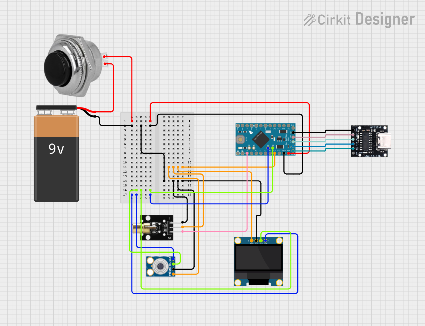
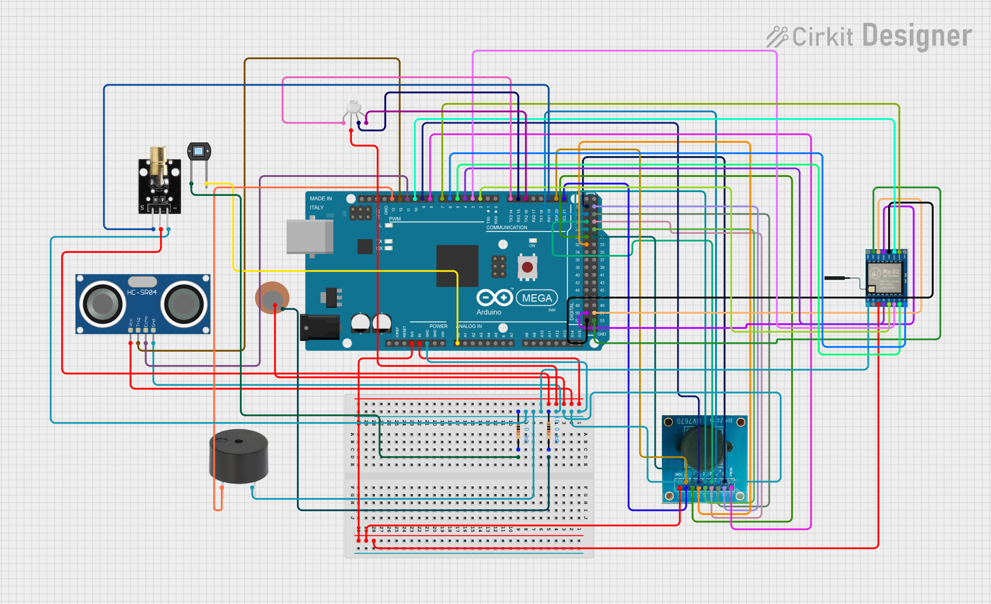
Explore Projects Built with Laser Sensor
Common Applications and Use Cases
- Industrial Automation: Object detection, positioning, and distance measurement in manufacturing lines.
- Robotics: Obstacle detection and navigation for autonomous systems.
- Security Systems: Intrusion detection and perimeter monitoring.
- Consumer Electronics: Proximity sensing in devices like smartphones and smart home systems.
- Automotive: Parking assistance and collision avoidance systems.
Technical Specifications
The following table outlines the key technical details of the OTC OT3660 Laser Sensor:
| Parameter | Specification |
|---|---|
| Manufacturer | OTC |
| Part ID | OT3660 |
| Operating Voltage | 5V DC |
| Operating Current | 30 mA (typical) |
| Detection Range | 2 cm to 400 cm |
| Accuracy | ±1 mm |
| Laser Wavelength | 650 nm (red, visible) |
| Beam Divergence | < 1 mrad |
| Response Time | < 10 ms |
| Operating Temperature | -10°C to 50°C |
| Communication Interface | Analog output / Digital (PWM) output |
Pin Configuration and Descriptions
The OT3660 Laser Sensor has a 4-pin interface. The pin configuration is as follows:
| Pin | Name | Description |
|---|---|---|
| 1 | VCC | Power supply input (5V DC) |
| 2 | GND | Ground connection |
| 3 | OUT | Output signal (analog voltage or PWM, depending on mode) |
| 4 | MODE | Mode selection (HIGH for PWM, LOW for analog output) |
Usage Instructions
How to Use the OT3660 Laser Sensor in a Circuit
- Power the Sensor: Connect the VCC pin to a 5V DC power source and the GND pin to the ground of your circuit.
- Select Output Mode: Use the MODE pin to select the desired output mode:
- Set MODE to HIGH for PWM output.
- Set MODE to LOW for analog voltage output.
- Read the Output:
- In analog mode, the OUT pin provides a voltage proportional to the detected distance.
- In PWM mode, the OUT pin outputs a pulse-width modulated signal, where the duty cycle corresponds to the distance.
- Connect to a Microcontroller: The sensor can be interfaced with a microcontroller (e.g., Arduino UNO) to process the output signal and calculate the distance.
Important Considerations and Best Practices
- Avoid Direct Eye Exposure: The laser beam is visible and can be harmful to the eyes. Do not look directly into the laser.
- Stable Power Supply: Ensure a stable 5V power supply to avoid measurement inaccuracies.
- Environmental Factors: The sensor's performance may be affected by reflective surfaces, ambient light, or extreme temperatures. Use appropriate shielding or calibration if necessary.
- Mounting: Securely mount the sensor to prevent vibrations or misalignment, which can affect accuracy.
Example: Connecting the OT3660 to an Arduino UNO
Below is an example of how to connect and use the OT3660 Laser Sensor with an Arduino UNO in analog mode:
Circuit Connections
- VCC: Connect to the Arduino's 5V pin.
- GND: Connect to the Arduino's GND pin.
- OUT: Connect to an analog input pin (e.g., A0) on the Arduino.
- MODE: Connect to GND for analog mode.
Arduino Code
// Define the analog input pin for the sensor
const int sensorPin = A0; // OUT pin of OT3660 connected to A0

void setup() {
  Serial.begin(9600); // Initialize serial communication at 9600 baud
}

void loop() {
  // Read the analog value from the sensor
  int sensorValue = analogRead(sensorPin);

  // Convert the analog value to a distance (example conversion factor)
  float distance = sensorValue * (400.0 / 1023.0); // Scale to 2-400 cm range

  // Print the distance to the Serial Monitor
  Serial.print("Distance: ");
  Serial.print(distance);
  Serial.println(" cm");

  delay(100); // Wait 100 ms before the next reading
}
Troubleshooting and FAQs
Common Issues and Solutions
No Output Signal:
- Ensure the sensor is powered correctly (5V to VCC, GND connected).
- Verify the MODE pin is set to the correct level (HIGH for PWM, LOW for analog).
- Check the wiring for loose or incorrect connections.
Inaccurate Distance Measurements:
- Ensure the target object is within the sensor's detection range (2 cm to 400 cm).
- Avoid using the sensor in environments with excessive ambient light or reflective surfaces.
- Verify the sensor is mounted securely and aligned properly.
Interference or Noise in Output:
- Use a decoupling capacitor (e.g., 0.1 µF) between VCC and GND to filter power supply noise.
- Shield the sensor from electromagnetic interference (EMI) sources.
FAQs
Q1: Can the OT3660 detect transparent objects?
A1: The sensor may have difficulty detecting transparent or highly reflective objects. For best results, use objects with a matte or diffuse surface.
Q2: What is the maximum cable length for connecting the sensor?
A2: The maximum cable length depends on the operating environment and signal integrity. For most applications, keep the cable length under 1 meter to minimize noise.
Q3: Can the sensor operate on a 3.3V power supply?
A3: No, the OT3660 requires a 5V DC power supply for proper operation.
Q4: How do I switch between analog and PWM modes?
A4: Use the MODE pin. Set it to HIGH for PWM output or LOW for analog voltage output.
By following this documentation, users can effectively integrate the OTC OT3660 Laser Sensor into their projects and troubleshoot common issues.