How to Use XFS5152CE: Examples, Pinouts, and Specs
Introduction
The XFS5152CE, manufactured by Shenzhen XunFei Silicon Technology Co., Ltd., is a high-performance, low-power, dual-channel analog front-end (AFE) designed for sensor applications. It integrates signal conditioning and analog-to-digital conversion (ADC) capabilities, making it an ideal choice for applications requiring precise signal processing and low power consumption.
Explore Projects Built with XFS5152CE


Explore Projects Built with XFS5152CE
Common Applications and Use Cases
- Industrial sensor systems
- Medical instrumentation
- Environmental monitoring
- IoT devices requiring analog signal acquisition
- Portable and battery-powered devices
Technical Specifications
Key Technical Details
| Parameter | Value |
|---|---|
| Supply Voltage | 2.7V to 5.5V |
| Power Consumption | < 1 mW (typical, at 3.3V supply) |
| Input Channels | 2 (dual-channel) |
| ADC Resolution | 16-bit |
| Sampling Rate | Up to 100 kSPS (kilo-samples per second) |
| Input Signal Range | 0V to VDD |
| Operating Temperature Range | -40°C to +85°C |
| Package Type | QFN-16 |
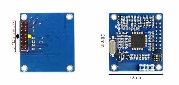
Pin Configuration and Descriptions
The XFS5152CE is housed in a 16-pin QFN package. Below is the pinout and description:
| Pin Number | Pin Name | Description |
|---|---|---|
| 1 | VDD | Power supply input (2.7V to 5.5V) |
| 2 | GND | Ground |
| 3 | IN1+ | Positive input for Channel 1 |
| 4 | IN1- | Negative input for Channel 1 |
| 5 | IN2+ | Positive input for Channel 2 |
| 6 | IN2- | Negative input for Channel 2 |
| 7 | REF | Reference voltage input |
| 8 | CLK | External clock input |
| 9 | SCL | I2C clock line |
| 10 | SDA | I2C data line |
| 11 | INT | Interrupt output |
| 12 | CS | Chip select for SPI |
| 13 | MISO | SPI Master-In-Slave-Out |
| 14 | MOSI | SPI Master-Out-Slave-In |
| 15 | SCK | SPI clock |
| 16 | NC | No connection (leave unconnected) |
Usage Instructions
How to Use the XFS5152CE in a Circuit
- Power Supply: Connect the VDD pin to a stable power source (2.7V to 5.5V) and GND to ground.
- Input Signal: Connect the analog signals to the IN1+/IN1- and IN2+/IN2- pins. Ensure the input signal range does not exceed the supply voltage (VDD).
- Reference Voltage: Provide a stable reference voltage to the REF pin. This determines the ADC's full-scale range.
- Communication Interface:
- For I2C communication, connect the SCL and SDA pins to the microcontroller's I2C lines.
- For SPI communication, connect CS, MISO, MOSI, and SCK to the corresponding SPI lines of the microcontroller.
- Clock Input: Provide an external clock signal to the CLK pin if required.
- Interrupt Handling: Use the INT pin to monitor interrupt signals for events like data ready or error conditions.
Important Considerations and Best Practices
- Decoupling Capacitors: Place a 0.1 µF ceramic capacitor close to the VDD pin to filter out noise.
- Input Impedance: Ensure the sensor or signal source driving the inputs has a low output impedance for accurate ADC readings.
- Reference Voltage Stability: Use a low-noise, stable reference voltage source to achieve optimal ADC performance.
- Communication Protocol: Configure the microcontroller to match the XFS5152CE's I2C or SPI settings (e.g., clock speed, addressing).
Example: Connecting to an Arduino UNO (I2C)
Below is an example of how to interface the XFS5152CE with an Arduino UNO using the I2C protocol:
Circuit Connections
| XFS5152CE Pin | Arduino UNO Pin |
|---|---|
| VDD | 3.3V |
| GND | GND |
| SCL | A5 (SCL) |
| SDA | A4 (SDA) |
| INT | Digital Pin 2 |
Arduino Code Example
#include <Wire.h> // Include the Wire library for I2C communication

#define XFS5152CE_ADDR 0x48 // Replace with the actual I2C address of the XFS5152CE

void setup() {
  Wire.begin(); // Initialize I2C communication
  Serial.begin(9600); // Start serial communication for debugging

  // Example: Configure the XFS5152CE (write to a configuration register)
  Wire.beginTransmission(XFS5152CE_ADDR);
  Wire.write(0x01); // Register address (example)
  Wire.write(0x80); // Configuration value (example)
  Wire.endTransmission();

  Serial.println("XFS5152CE initialized.");
}

void loop() {
  // Example: Read ADC data from the XFS5152CE
  Wire.beginTransmission(XFS5152CE_ADDR);
  Wire.write(0x00); // Register address to read ADC data
  Wire.endTransmission();

  Wire.requestFrom(XFS5152CE_ADDR, 2); // Request 2 bytes of data
  if (Wire.available() == 2) {
    uint16_t adcValue = (Wire.read() << 8) | Wire.read(); // Combine MSB and LSB
    Serial.print("ADC Value: ");
    Serial.println(adcValue);
  }

  delay(500); // Wait for 500ms before the next reading
}
Troubleshooting and FAQs
Common Issues and Solutions
No Communication with the Device
- Cause: Incorrect I2C or SPI connections.
- Solution: Double-check the wiring and ensure the microcontroller's communication settings match the XFS5152CE.
Unstable ADC Readings
- Cause: Noisy power supply or unstable reference voltage.
- Solution: Use decoupling capacitors and a low-noise reference voltage source.
Device Not Responding
- Cause: Incorrect I2C address or SPI configuration.
- Solution: Verify the I2C address or SPI settings in the datasheet and update the code accordingly.
Overvoltage on Input Pins
- Cause: Input signal exceeds the supply voltage (VDD).
- Solution: Ensure the input signal range is within 0V to VDD.
FAQs
Q: Can the XFS5152CE operate with a 5V microcontroller?
A: Yes, the XFS5152CE supports a supply voltage up to 5.5V, making it compatible with 5V systems.Q: What is the maximum sampling rate of the ADC?
A: The ADC supports a maximum sampling rate of 100 kSPS.Q: Does the XFS5152CE support differential input signals?
A: Yes, the XFS5152CE supports differential input signals on both channels.Q: Can I use the XFS5152CE in a battery-powered application?
A: Yes, its low power consumption (< 1 mW) makes it suitable for battery-powered devices.