How to Use ZS-X11H v2 350w Motor Controller: Examples, Pinouts, and Specs
Introduction
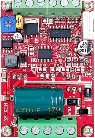
The ZS-X11H v2 350w Motor Controller by RioRand is an advanced electronic device designed to control the speed and direction of a 350w brushless motor. It is widely used in applications such as electric bicycles, scooters, and other personal mobility devices. The controller offers features like over-current protection, under-voltage protection, and speed adjustment, making it a versatile choice for various motor control needs.
Explore Projects Built with ZS-X11H v2 350w Motor Controller


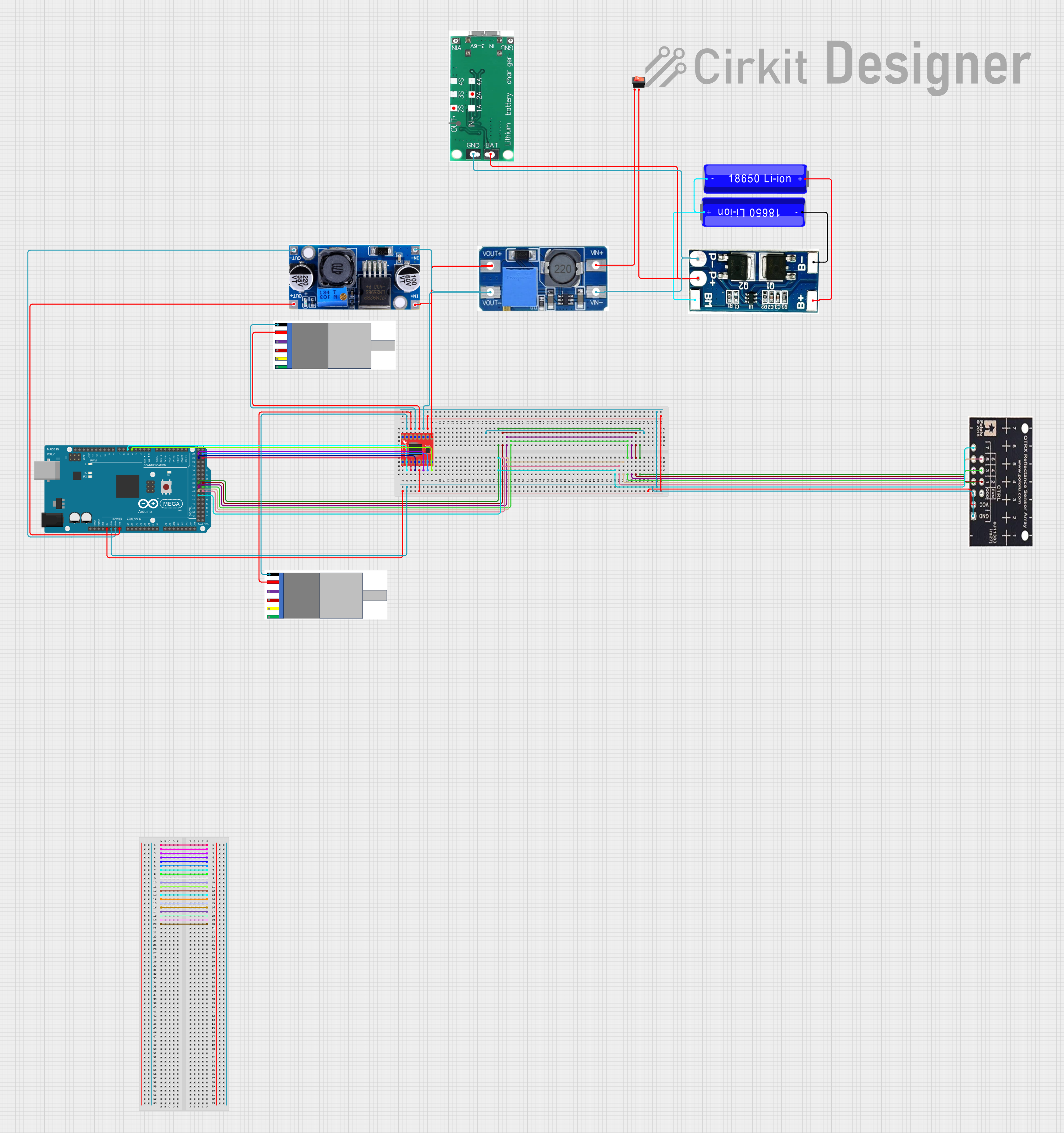
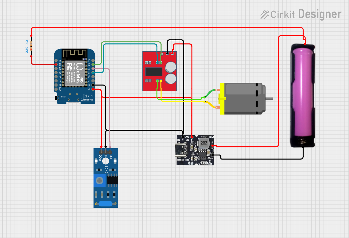
Explore Projects Built with ZS-X11H v2 350w Motor Controller
Technical Specifications
Key Technical Details
- Rated Voltage: DC 36V/48V (Universal)
- Max Current: 15A
- Rated Power: 350W
- Protection Class: IPX5
- Operating Temperature: -20°C to 50°C
Pin Configuration and Descriptions
| Pin Number | Description | Notes |
|---|---|---|
| 1 | Battery + (B+) | Connect to battery positive |
| 2 | Battery - (B-) | Connect to battery negative |
| 3 | Motor Phase (M) | Connect to motor phase wire |
| 4 | Motor Hall (H) | Connect to motor hall sensor |
| 5 | Throttle (THR) | Connect to throttle signal input |
| 6 | Brake (BRK) | Connect to brake switch |
| 7 | Speed Limit (SL) | Speed limit signal (optional) |
| 8 | Reverse (REV) | Reverse function (optional) |
| 9 | Indicator LED+ (LED+) | Connect to indicator LED positive |
| 10 | Indicator LED- (LED-) | Connect to indicator LED negative |
Usage Instructions
How to Use the Component in a Circuit
Power Connections:
- Connect the battery's positive and negative terminals to the B+ and B- pins, respectively.
- Ensure that the battery voltage matches the controller's rated voltage.
Motor Connections:
- Connect the motor phase wire to the M pin.
- Connect the motor hall sensor to the H pin.
Control Inputs:
- Connect the throttle signal input to the THR pin for speed control.
- If a brake switch is used, connect it to the BRK pin.
- For optional speed limiting, connect the speed limit signal to the SL pin.
- For optional reverse functionality, connect the reverse function to the REV pin.
Indicator LED:
- Connect the indicator LED positive and negative to the LED+ and LED- pins, respectively.
Important Considerations and Best Practices
- Always disconnect the battery before making or changing connections.
- Use appropriate wire gauges to handle the current requirements.
- Ensure all connections are secure and insulated to prevent short circuits.
- Do not exceed the rated voltage and current specifications.
- Mount the controller in a location with adequate ventilation to prevent overheating.
Troubleshooting and FAQs
Common Issues
- Motor not responding: Check all connections, ensure the battery is charged, and the throttle is properly connected.
- Overheating: Ensure the controller is mounted in a well-ventilated area and not overloaded.
- Erratic behavior: Verify that there are no loose connections and that the motor and controller are compatible.
Solutions and Tips for Troubleshooting
- Double-check wiring against the pin configuration table.
- Use a multimeter to verify the presence of voltage at the appropriate pins.
- If the motor jitters or doesn't run smoothly, check the hall sensor connections.
FAQs
Q: Can I use this controller with a motor rated higher than 350w? A: It is not recommended as it may cause the controller to overheat and fail.
Q: What should I do if the controller gets wet? A: Disconnect the power immediately and allow the controller to dry completely before use.
Q: Can I use this controller without a hall sensor? A: This controller is designed for use with brushless motors that have hall sensors. Using it without a hall sensor may result in improper function.
Example Arduino UNO Connection (Optional)
// Example code to control ZS-X11H v2 Motor Controller with Arduino UNO
// This code assumes you have a potentiometer connected to A0 for throttle control

const int throttlePin = A0; // Potentiometer connected to A0
const int throttleControlPin = 9; // PWM output to THR pin on controller

void setup() {
  pinMode(throttleControlPin, OUTPUT);
  analogWrite(throttleControlPin, 0); // Initialize with 0 throttle
}

void loop() {
  int throttleValue = analogRead(throttlePin); // Read the potentiometer
  int throttlePWM = map(throttleValue, 0, 1023, 0, 255); // Map to PWM range
  analogWrite(throttleControlPin, throttlePWM); // Send PWM signal to controller
  delay(10); // Short delay for stability
}
Note: The above code is a simple example to demonstrate how the ZS-X11H v2 Motor Controller can be interfaced with an Arduino UNO for throttle control. The actual implementation may vary based on the specific application and additional features such as braking or reversing. Always ensure that the controller's input voltage requirements are met when interfacing with any microcontroller.