Cirkit Designer Logo
Cirkit Designer
Your all-in-one circuit design IDE
Home / 
Component Documentation

How to Use Switching step-up voltage regulator: Examples, Pinouts, and Specs

Image of Switching step-up voltage regulator
Cirkit Designer LogoDesign with Switching step-up voltage regulator in Cirkit Designer

Introduction

A switching step-up voltage regulator, also known as a boost converter, is an essential electronic component that efficiently increases a lower input voltage to a higher output voltage through the use of inductors, diodes, and capacitors. This type of regulator is widely used in battery-powered devices, portable electronics, and LED drivers where a consistent and higher voltage output is necessary from a lower voltage source.

Explore Projects Built with Switching step-up voltage regulator

Use Cirkit Designer to design, explore, and prototype these projects online. Some projects support real-time simulation. Click "Open Project" to start designing instantly!
Battery-Powered UPS with Step-Down Buck Converter and BMS
Image of Mini ups: A project utilizing Switching step-up voltage regulator in a practical application
This circuit is a power management system that steps down a 240V AC input to a lower DC voltage using a buck converter, which then powers a 40W UPS. The UPS is controlled by a rocker switch and is backed up by a battery management system (BMS) connected to three 3.7V batteries in series, ensuring continuous power supply.
Cirkit Designer LogoOpen Project in Cirkit Designer
Battery-Powered High Voltage Generator with Copper Coil
Image of Ionic Thruster Mark_1: A project utilizing Switching step-up voltage regulator in a practical application
This circuit consists of a Li-ion battery connected to a step-up power module through a rocker switch, which boosts the voltage to power a ring of copper gauge with an aluminum frame. The rocker switch allows the user to control the power flow from the battery to the step-up module, which then supplies the boosted voltage to the copper ring.
Cirkit Designer LogoOpen Project in Cirkit Designer
Battery-Powered DC Generator with XL4015 Buck Converter
Image of conveyor: A project utilizing Switching step-up voltage regulator in a practical application
This circuit consists of a 12V battery connected to a rocker switch, which controls the input to an XL4015 DC Buck Step-down converter. The converter steps down the voltage to power a DC generator, with the generator's output connected back to the converter to form a feedback loop.
Cirkit Designer LogoOpen Project in Cirkit Designer
Multi-Stage Voltage Regulation and Indicator LED Circuit
Image of Subramanyak_Power_Circuit: A project utilizing Switching step-up voltage regulator in a practical application
This circuit is designed for power management, featuring buck and boost converters for voltage adjustment, and linear regulators for stable voltage output. It includes LEDs for status indication, and terminal blocks for external connections.
Cirkit Designer LogoOpen Project in Cirkit Designer

Explore Projects Built with Switching step-up voltage regulator

Use Cirkit Designer to design, explore, and prototype these projects online. Some projects support real-time simulation. Click "Open Project" to start designing instantly!
Image of Mini ups: A project utilizing Switching step-up voltage regulator in a practical application
Battery-Powered UPS with Step-Down Buck Converter and BMS
This circuit is a power management system that steps down a 240V AC input to a lower DC voltage using a buck converter, which then powers a 40W UPS. The UPS is controlled by a rocker switch and is backed up by a battery management system (BMS) connected to three 3.7V batteries in series, ensuring continuous power supply.
Cirkit Designer LogoOpen Project in Cirkit Designer
Image of Ionic Thruster Mark_1: A project utilizing Switching step-up voltage regulator in a practical application
Battery-Powered High Voltage Generator with Copper Coil
This circuit consists of a Li-ion battery connected to a step-up power module through a rocker switch, which boosts the voltage to power a ring of copper gauge with an aluminum frame. The rocker switch allows the user to control the power flow from the battery to the step-up module, which then supplies the boosted voltage to the copper ring.
Cirkit Designer LogoOpen Project in Cirkit Designer
Image of conveyor: A project utilizing Switching step-up voltage regulator in a practical application
Battery-Powered DC Generator with XL4015 Buck Converter
This circuit consists of a 12V battery connected to a rocker switch, which controls the input to an XL4015 DC Buck Step-down converter. The converter steps down the voltage to power a DC generator, with the generator's output connected back to the converter to form a feedback loop.
Cirkit Designer LogoOpen Project in Cirkit Designer
Image of Subramanyak_Power_Circuit: A project utilizing Switching step-up voltage regulator in a practical application
Multi-Stage Voltage Regulation and Indicator LED Circuit
This circuit is designed for power management, featuring buck and boost converters for voltage adjustment, and linear regulators for stable voltage output. It includes LEDs for status indication, and terminal blocks for external connections.
Cirkit Designer LogoOpen Project in Cirkit Designer

Common Applications and Use Cases

  • Powering 5V or 12V circuits from a single-cell battery
  • Driving high-power LEDs from low-voltage sources
  • Boosting voltage for small electric motors
  • Portable electronic devices requiring stable voltage supply
  • Energy harvesting applications such as solar panels

Technical Specifications

Key Technical Details

Parameter Specification Notes
Input Voltage (Vin) 2.0V to 15V Minimum and maximum input voltage
Output Voltage (Vout) 2.5V to 35V Adjustable via external components
Switching Frequency 50kHz to 1MHz Varies by specific model
Maximum Output Current 1A to 3A Depends on input voltage and heat dissipation
Efficiency Up to 95% Varies with load and input voltage

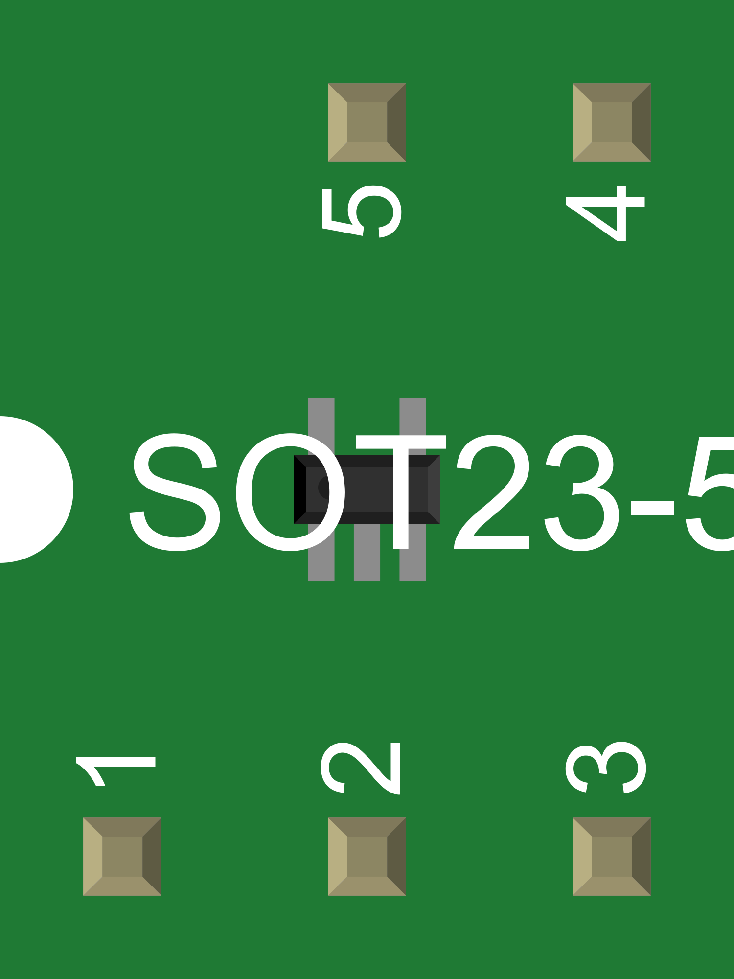
Pin Configuration and Descriptions

Pin Number Name Description
1 GND Ground connection
2 VIN Input voltage supply
3 SW Switch node, connects to inductor
4 FB Feedback pin, sets output voltage
5 EN Enable pin, turns regulator on/off
6 VOUT Regulated output voltage

Usage Instructions

How to Use the Component in a Circuit

  1. Connect the input voltage source to the VIN and GND pins.
  2. Attach an inductor between the SW pin and the desired output node.
  3. Connect a diode from the output node to the VOUT pin, ensuring correct polarity.
  4. Place a capacitor between VOUT and GND to smooth the output voltage.
  5. Set the desired output voltage by selecting the right resistor divider network connected to the FB pin.
  6. Optionally, control the EN pin to turn the regulator on or off as needed.

Important Considerations and Best Practices

  • Always use capacitors with low equivalent series resistance (ESR) for better performance.
  • Ensure the inductor's current rating is above the maximum load current.
  • Use a diode with a reverse voltage rating higher than the maximum output voltage and a forward current rating above the maximum load current.
  • Place input and output capacitors as close to the regulator pins as possible to minimize noise and improve stability.
  • Avoid long wire runs to reduce voltage drops and electromagnetic interference (EMI).

Troubleshooting and FAQs

Common Issues Users Might Face

  • Output voltage is too low or unstable: Check the feedback network and ensure the output capacitor is of good quality and properly rated.
  • Regulator is overheating: Ensure the current draw is within specifications and improve heat dissipation with a heatsink if necessary.
  • No output voltage: Verify the input voltage is within range and the EN pin is correctly driven.

Solutions and Tips for Troubleshooting

  • If the output voltage is not correct, recheck the resistor values in the feedback network.
  • For overheating issues, reduce the load or improve cooling.
  • Confirm that all connections are secure and components are not damaged.

FAQs

Q: Can I adjust the output voltage? A: Yes, by changing the resistor values in the feedback network connected to the FB pin.

Q: What is the maximum input voltage I can apply? A: The maximum input voltage is typically 15V, but always refer to the specific model's datasheet.

Q: How do I enable or disable the regulator? A: Apply a high signal to the EN pin to enable and a low signal or ground to disable the regulator.

Example Code for Arduino UNO

// Example code to control a switching step-up voltage regulator's EN pin using Arduino UNO

const int enablePin = 7; // Connect the EN pin of the regulator to digital pin 7

void setup() {
  pinMode(enablePin, OUTPUT); // Set the enable pin as an output
}

void loop() {
  digitalWrite(enablePin, HIGH); // Enable the step-up regulator
  delay(5000);                  // Wait for 5 seconds
  digitalWrite(enablePin, LOW);  // Disable the step-up regulator
  delay(5000);                  // Wait for 5 seconds
}

Remember to adjust the pin number in the code to match your actual setup. The above code simply turns the regulator on and off every 5 seconds.