How to Use KY-004 Key Switch Module: Examples, Pinouts, and Specs
Introduction
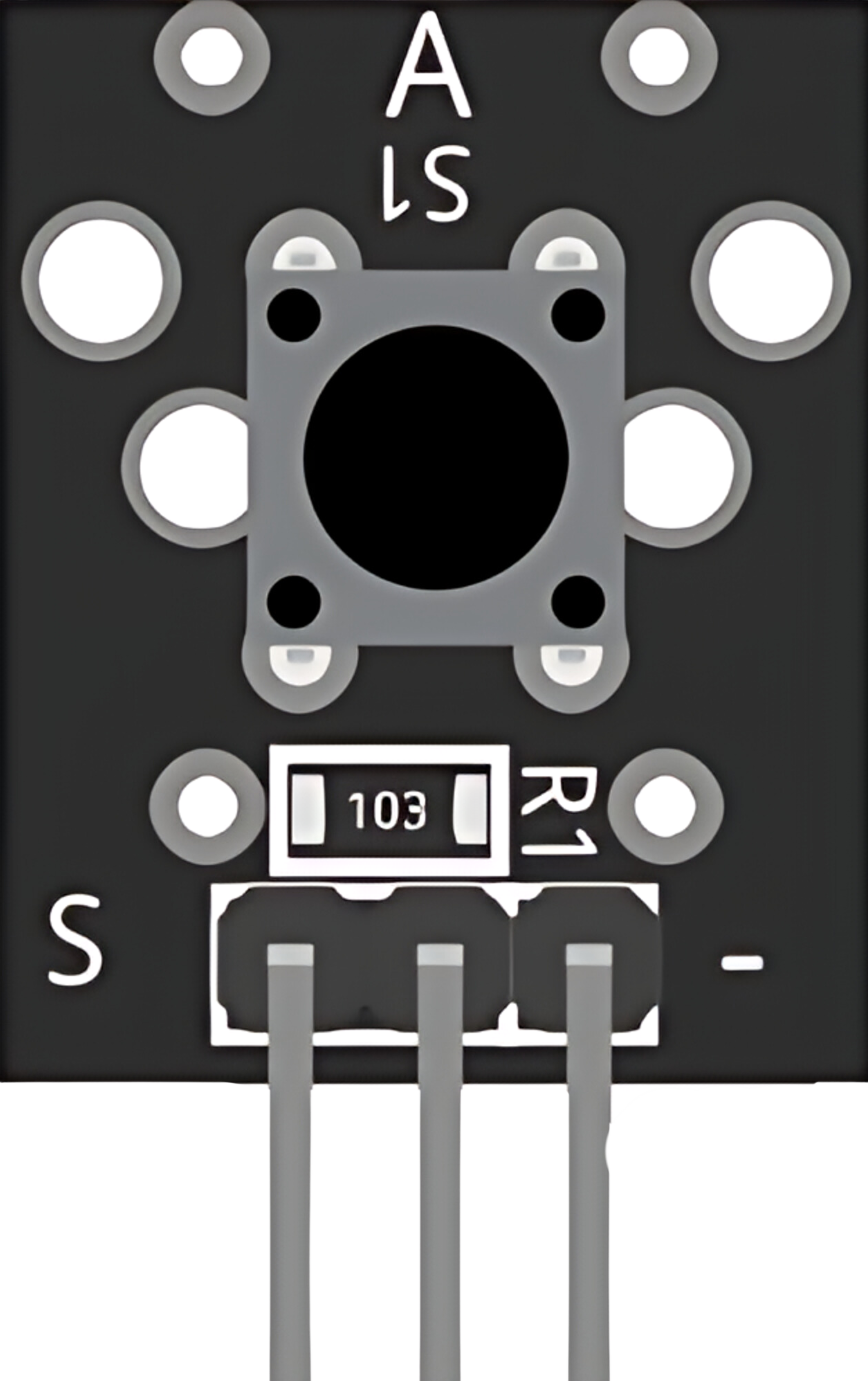
The KY-004 Key Switch Module is a compact and versatile input device that integrates a tactile pushbutton switch. It is widely used in electronics projects for user input, allowing for simple on/off control. This module is particularly popular in hobbyist projects, including those involving microcontrollers like the Arduino UNO.
Explore Projects Built with KY-004 Key Switch Module
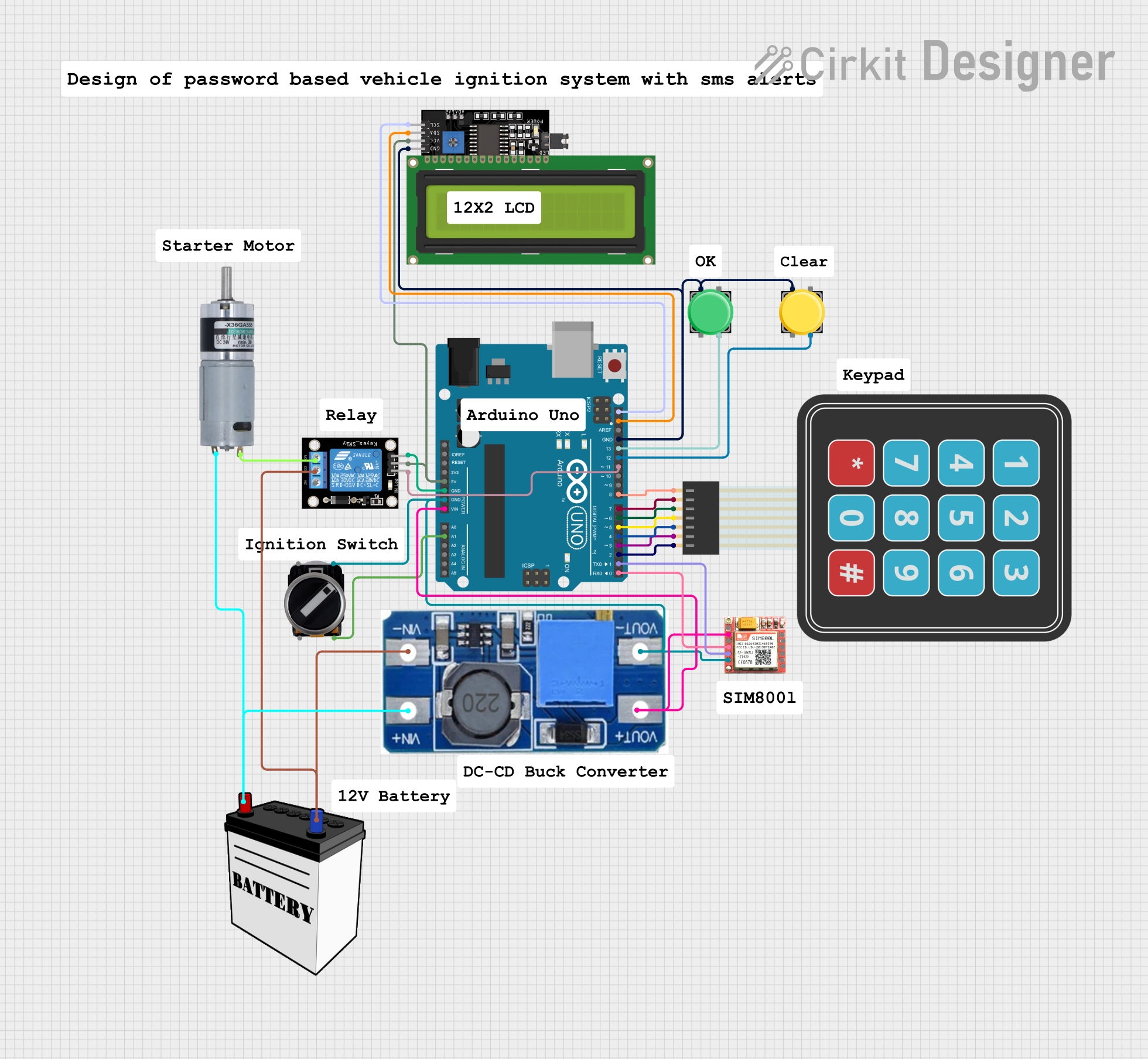

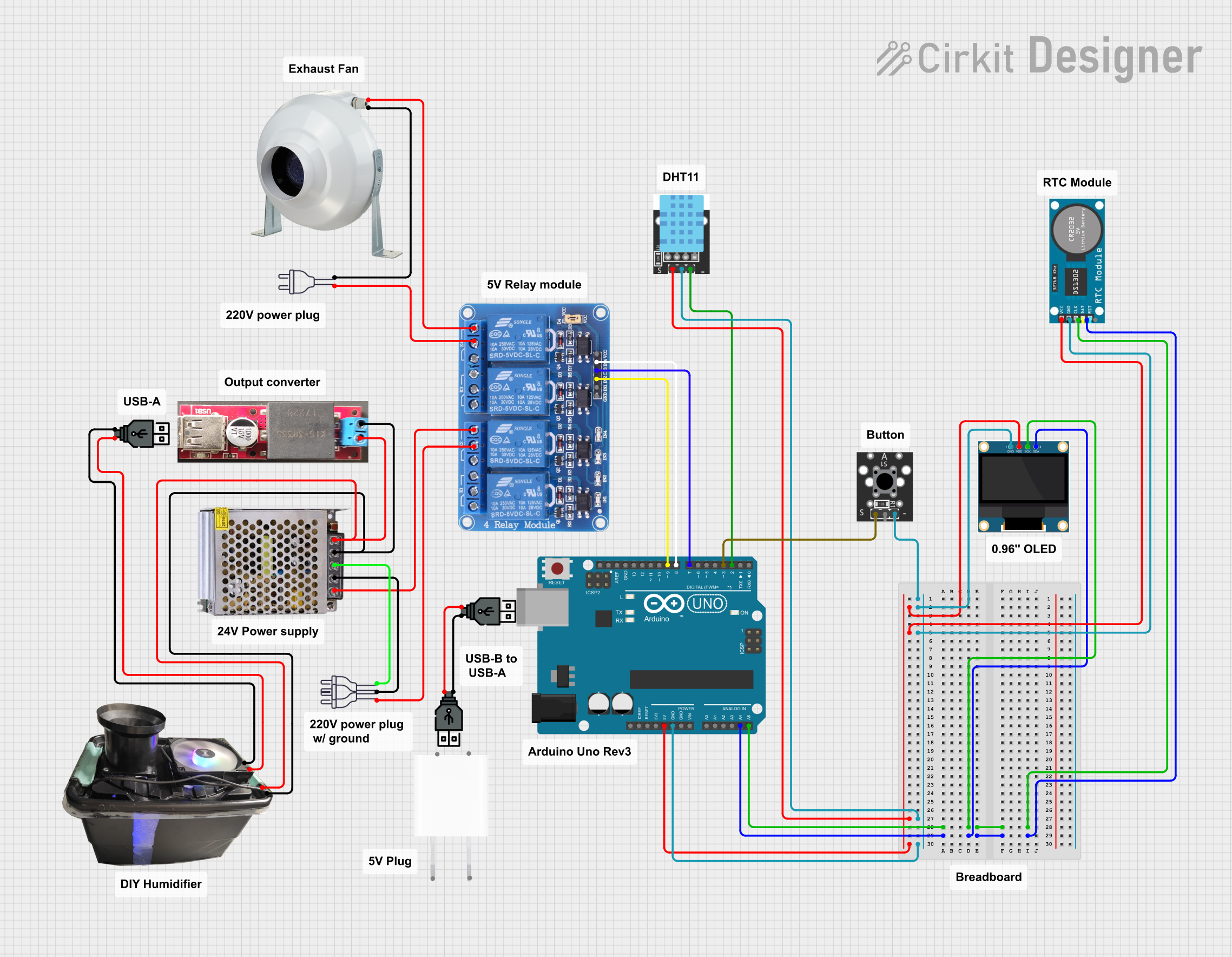

Explore Projects Built with KY-004 Key Switch Module
Common Applications and Use Cases
- User interfaces for electronic devices
- Input control for microcontroller projects
- Prototyping and educational tools for learning electronics
- Interactive installations and exhibits
Technical Specifications
Key Technical Details
- Operating Voltage: 3.3V to 5V
- Output Type: Digital signal
- Contact Type: Normally open
Pin Configuration and Descriptions
| Pin Number | Description |
|---|---|
| 1 | Signal (S) |
| 2 | Ground (GND) |
| 3 | Voltage Supply (V) |
Usage Instructions
How to Use the Component in a Circuit
- Connect the V pin to the 3.3V or 5V power supply of your microcontroller or power source.
- Connect the GND pin to the ground of your power source or microcontroller.
- Connect the S pin to a digital input pin on your microcontroller.
Important Considerations and Best Practices
- Use a pull-up or pull-down resistor to ensure a stable signal when the switch is open.
- Debounce the switch in software to prevent false triggering from mechanical vibrations.
- Avoid applying voltage higher than the recommended operating voltage to prevent damage.
Example Code for Arduino UNO
// Define the pin connected to the KY-004 module
const int buttonPin = 2;

// Variable for storing the button state
int buttonState = 0;

void setup() {
  // Initialize the button pin as an input
  pinMode(buttonPin, INPUT);
}

void loop() {
  // Read the state of the button
  buttonState = digitalRead(buttonPin);

  // Check if the button is pressed
  if (buttonState == HIGH) {
    // If the button is pressed, do something
    // ...
  } else {
    // If the button is not pressed, do something else
    // ...
  }
}
Note: The above code assumes that the KY-004 module is connected with a pull-up resistor. If you're using the internal pull-up resistor of the Arduino, you can initialize the button pin with pinMode(buttonPin, INPUT_PULLUP);.
Troubleshooting and FAQs
Common Issues Users Might Face
- Button not responding: Ensure that all connections are secure and the power supply is within the operating voltage range.
- Unstable button readings: Implement software debouncing or check the pull-up/pull-down resistor.
Solutions and Tips for Troubleshooting
- Check Connections: Double-check wiring against the pin configuration table.
- Debounce the Button: Use software debouncing techniques to filter out spurious signals.
- Test with a Multimeter: Use a multimeter to ensure the button is functioning correctly when pressed.
FAQs
Q: Can I use the KY-004 module with a 3.3V system?
- A: Yes, the KY-004 can operate within a 3.3V to 5V range.
Q: How do I know if the button is pressed in my code?
- A: The digitalRead function will return HIGH if the button is pressed, assuming a pull-up resistor is used.
Q: What is the purpose of the pull-up resistor?
- A: The pull-up resistor ensures that the input pin is at a known voltage when the switch is open (not pressed).
This documentation provides a comprehensive guide to using the KY-004 Key Switch Module in your projects. For further assistance, consult the community forums or technical support of your microcontroller platform.