
How to Use PCF8575: Examples, Pinouts, and Specs
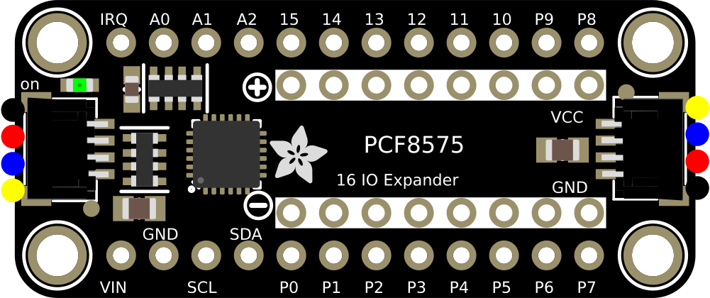
 Design with PCF8575 in Cirkit Designer
Introduction
The PCF8575 is a 16-bit I/O expander that communicates via the I2C protocol, enabling microcontrollers to expand their GPIO capabilities. It features two 8-bit ports (Port 0 and Port 1), which can be configured as inputs or outputs. This component is ideal for applications requiring additional GPIO pins without increasing the microcontroller's pin usage. The PCF8575 is commonly used in projects involving LED control, keypad interfacing, sensor integration, and other peripheral expansions.
Explore Projects Built with PCF8575
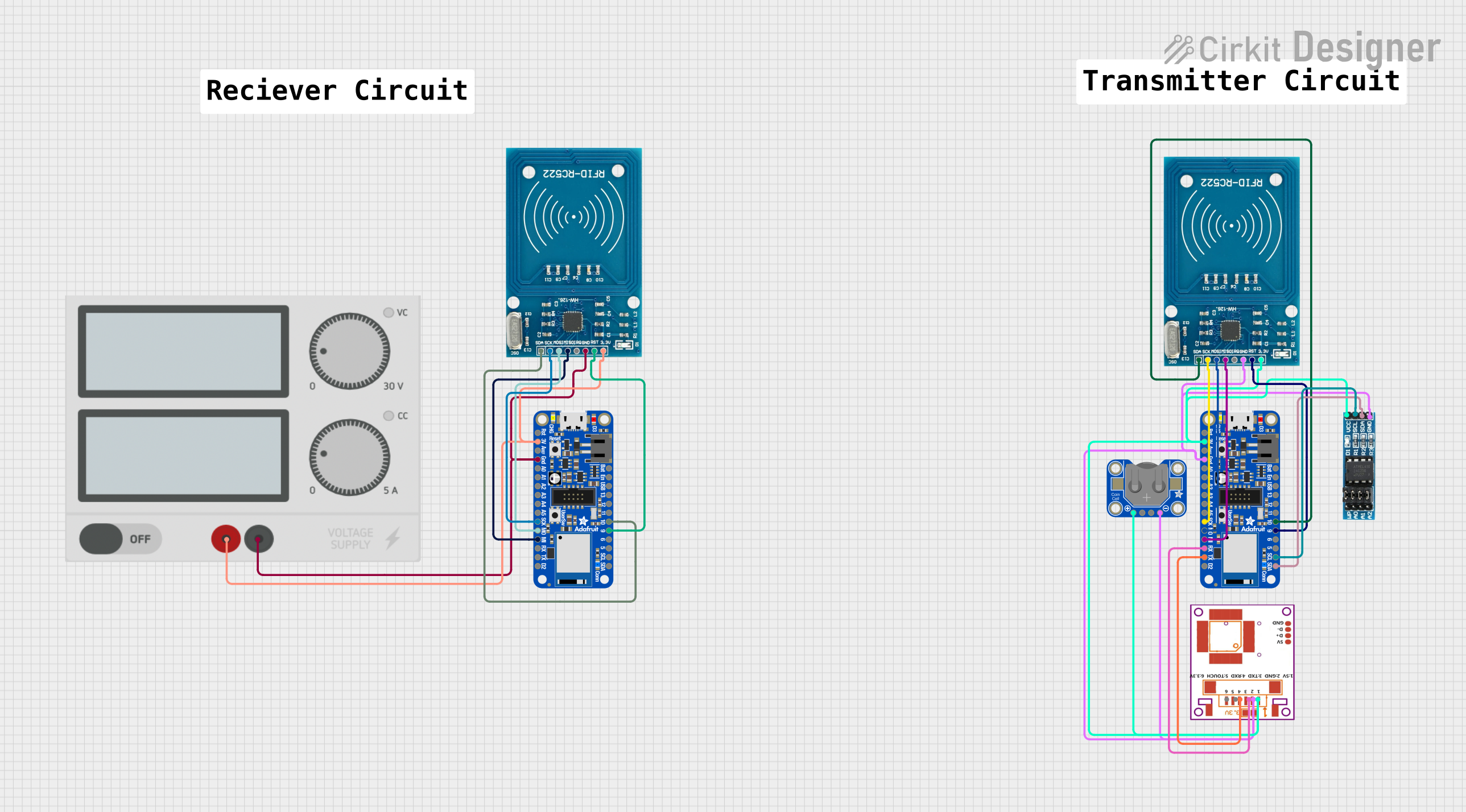 Open Project in Cirkit Designer
 Open Project in Cirkit Designer
 Open Project in Cirkit Designer
 Open Project in Cirkit Designer
Explore Projects Built with PCF8575
Open Project in Cirkit DesignerOpen Project in Cirkit DesignerOpen Project in Cirkit DesignerOpen Project in Cirkit DesignerCommon Applications:
- Expanding GPIO pins in microcontroller-based systems
- Driving LEDs, relays, or other output devices
- Reading inputs from switches, keypads, or sensors
- I2C-based communication for efficient pin management
Technical Specifications
Below are the key technical details of the PCF8575:
| Parameter | Value |
|---|---|
| Operating Voltage | 2.5V to 5.5V |
| I2C Communication Speed | Up to 400 kHz (Fast Mode) |
| Number of I/O Pins | 16 (2 ports, 8 bits each) |
| Input High Voltage (VIH) | 0.7 × VDD (minimum) |
| Input Low Voltage (VIL) | 0.3 × VDD (maximum) |
| Output Low Current | 25 mA (maximum per pin) |
| Output High Current | -25 mA (maximum per pin) |
| I2C Address Range | 0x20 to 0x27 (configurable via A0, A1, A2 pins) |
| Package Types | SOIC, TSSOP, DIP |
Pin Configuration and Descriptions
The PCF8575 has 16 GPIO pins divided into two 8-bit ports (P0 and P1) and additional pins for power, ground, and I2C communication.
| Pin | Name | Description |
|---|---|---|
| 1 | P00 | Port 0, Bit 0 (GPIO) |
| 2 | P01 | Port 0, Bit 1 (GPIO) |
| 3 | P02 | Port 0, Bit 2 (GPIO) |
| 4 | P03 | Port 0, Bit 3 (GPIO) |
| 5 | P04 | Port 0, Bit 4 (GPIO) |
| 6 | P05 | Port 0, Bit 5 (GPIO) |
| 7 | P06 | Port 0, Bit 6 (GPIO) |
| 8 | P07 | Port 0, Bit 7 (GPIO) |
| 9 | GND | Ground |
| 10 | SDA | I2C Data Line |
| 11 | SCL | I2C Clock Line |
| 12 | /INT | Interrupt Output (active low) |
| 13 | P10 | Port 1, Bit 0 (GPIO) |
| 14 | P11 | Port 1, Bit 1 (GPIO) |
| 15 | P12 | Port 1, Bit 2 (GPIO) |
| 16 | P13 | Port 1, Bit 3 (GPIO) |
| 17 | P14 | Port 1, Bit 4 (GPIO) |
| 18 | P15 | Port 1, Bit 5 (GPIO) |
| 19 | P16 | Port 1, Bit 6 (GPIO) |
| 20 | P17 | Port 1, Bit 7 (GPIO) |
| 21 | A0 | I2C Address Selection Bit 0 |
| 22 | A1 | I2C Address Selection Bit 1 |
| 23 | A2 | I2C Address Selection Bit 2 |
| 24 | VCC | Power Supply |
Usage Instructions
Connecting the PCF8575 to a Microcontroller
- Power Supply: Connect the VCC pin to a 3.3V or 5V power source and the GND pin to ground.
- I2C Communication: Connect the SDA and SCL pins to the corresponding I2C pins on the microcontroller. Use pull-up resistors (typically 4.7kΩ) on both lines.
- Address Configuration: Set the I2C address by connecting A0, A1, and A2 to either VCC (logic high) or GND (logic low).
- GPIO Pins: Connect the desired peripherals (e.g., LEDs, switches) to the GPIO pins (P00–P07 and P10–P17).
Example Code for Arduino UNO
The following example demonstrates how to use the PCF8575 with an Arduino UNO to toggle an LED connected to P00.
#include <Wire.h> // Include the Wire library for I2C communication

#define PCF8575_ADDRESS 0x20 // Default I2C address of the PCF8575

void setup() {
  Wire.begin(); // Initialize I2C communication
  Serial.begin(9600); // Initialize serial communication for debugging

  // Set all pins to output and turn them off
  Wire.beginTransmission(PCF8575_ADDRESS);
  Wire.write(0x00); // Low byte (P00-P07)
  Wire.write(0x00); // High byte (P10-P17)
  Wire.endTransmission();
}

void loop() {
  // Turn on the LED connected to P00
  Wire.beginTransmission(PCF8575_ADDRESS);
  Wire.write(0x01); // Set P00 high, others low
  Wire.write(0x00); // High byte remains low
  Wire.endTransmission();
  delay(1000); // Wait for 1 second

  // Turn off the LED connected to P00
  Wire.beginTransmission(PCF8575_ADDRESS);
  Wire.write(0x00); // Set all low
  Wire.write(0x00); // High byte remains low
  Wire.endTransmission();
  delay(1000); // Wait for 1 second
}
Best Practices
- Use pull-up resistors on the SDA and SCL lines for reliable I2C communication.
- Avoid exceeding the maximum current ratings for the GPIO pins.
- Debounce input signals (e.g., from switches) in software to avoid erratic behavior.
- Use decoupling capacitors (e.g., 0.1 µF) near the VCC pin to reduce noise.
Troubleshooting and FAQs
Common Issues
No Response from the PCF8575:
- Ensure the I2C address matches the configuration of the A0, A1, and A2 pins.
- Verify the pull-up resistors on the SDA and SCL lines are correctly connected.
- Check the power supply voltage (2.5V–5.5V).
Incorrect GPIO Behavior:
- Confirm the GPIO pins are correctly configured as inputs or outputs.
- Check for short circuits or excessive current draw on the GPIO pins.
I2C Communication Errors:
- Ensure the I2C clock speed does not exceed 400 kHz.
- Verify the connections between the microcontroller and the PCF8575.
FAQs
Q: Can the PCF8575 handle analog signals?
A: No, the PCF8575 is designed for digital I/O only. It cannot process analog signals.
Q: How many PCF8575 devices can be connected to the same I2C bus?
A: Up to 8 devices can be connected by configuring unique I2C addresses using the A0, A1, and A2 pins.
Q: What happens if the power supply voltage exceeds 5.5V?
A: Exceeding the maximum voltage can damage the PCF8575. Always ensure the supply voltage is within the specified range.
Q: Can I use the PCF8575 with a 3.3V microcontroller?
A: Yes, the PCF8575 operates at 2.5V–5.5V, making it compatible with both 3.3V and 5V systems.