How to Use ADC IC: Examples, Pinouts, and Specs
Introduction
The AD7606 is a high-performance, 16-bit Analog-to-Digital Converter (ADC) IC manufactured by Analog Devices. It is designed to convert analog signals into precise digital data, enabling seamless integration of real-world signals into digital systems. The AD7606 is particularly well-suited for applications requiring simultaneous sampling of multiple channels, high accuracy, and robust performance in noisy environments.
Explore Projects Built with ADC IC

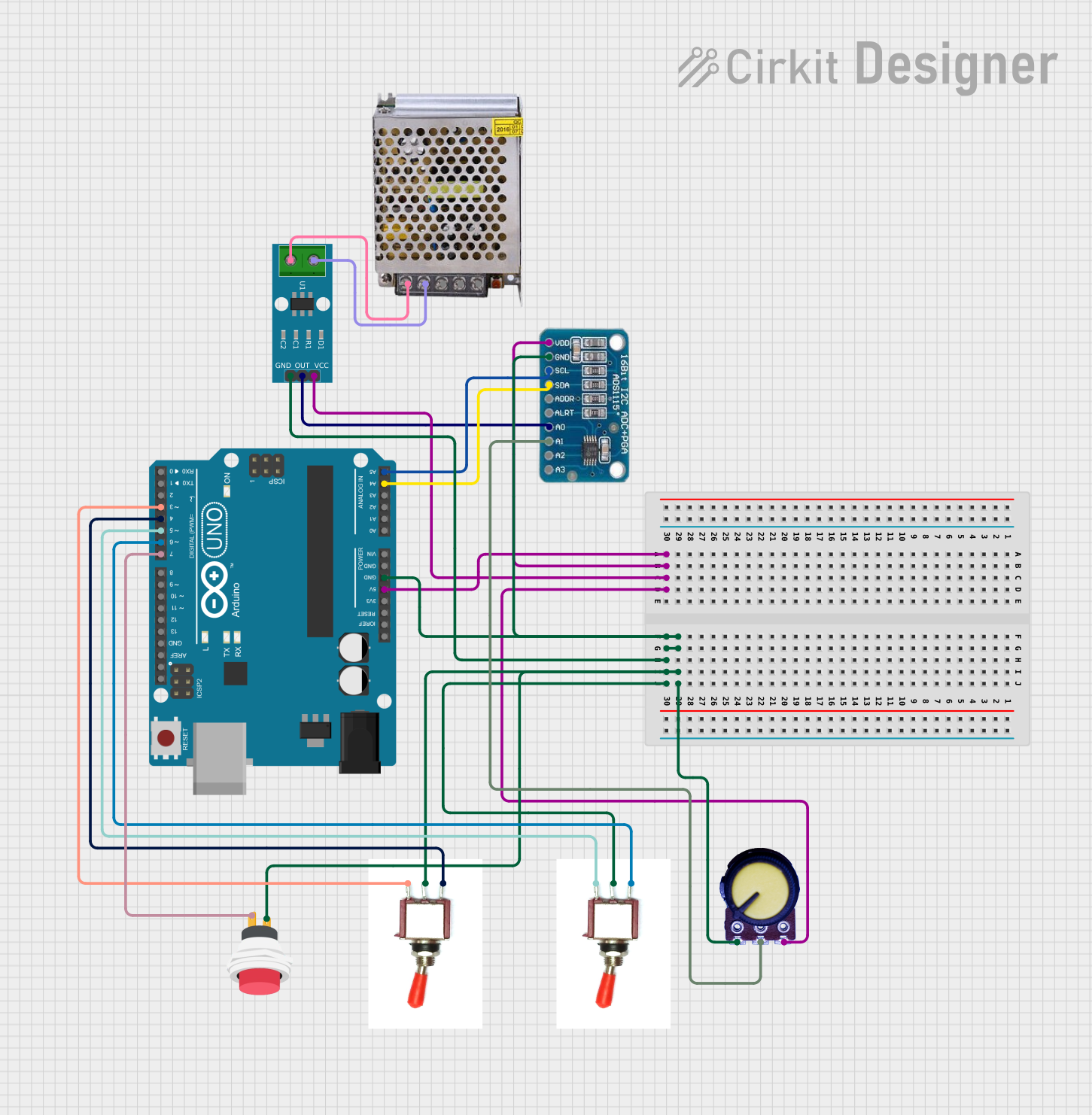
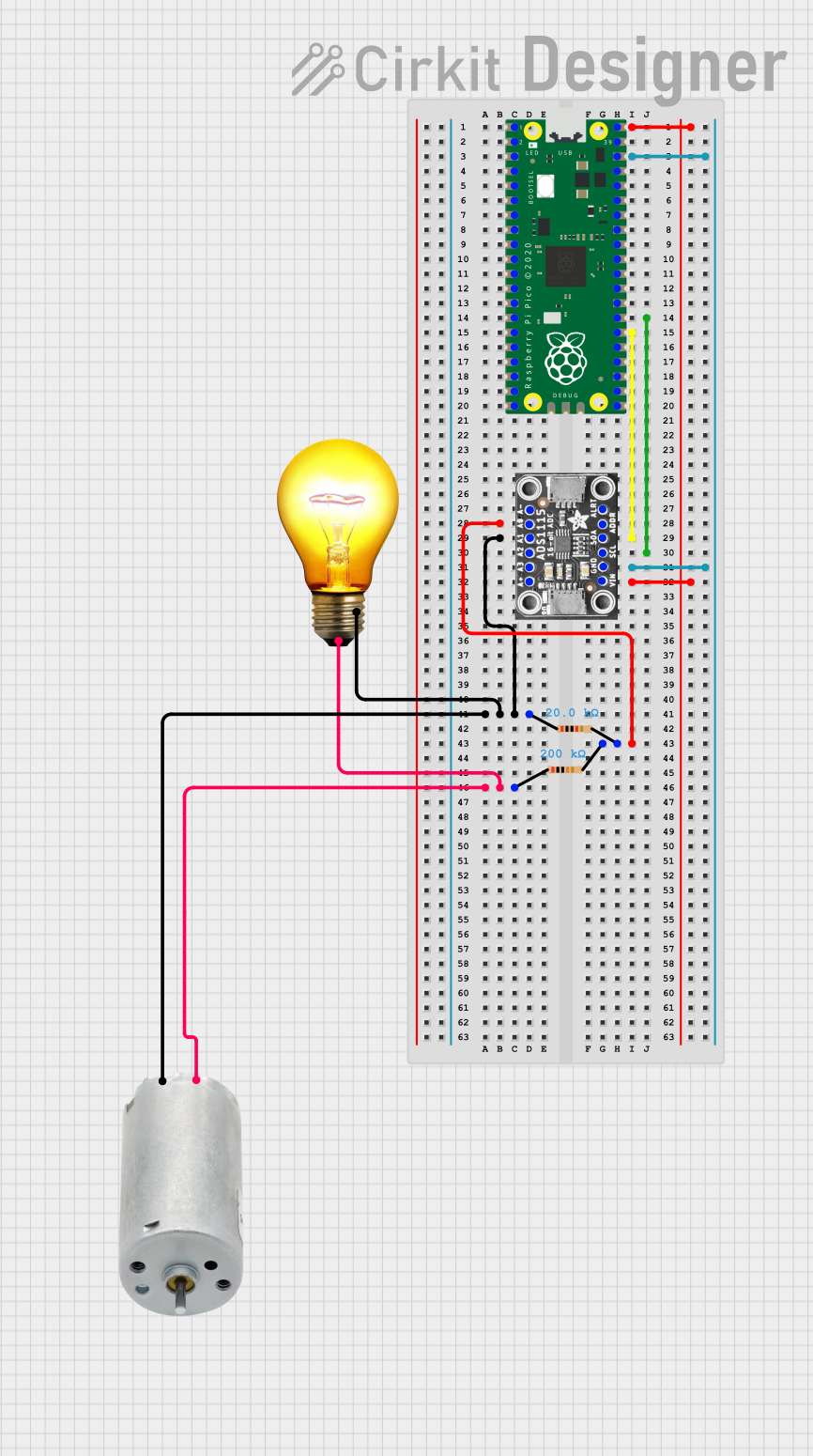

Explore Projects Built with ADC IC
Common Applications and Use Cases
- Data acquisition systems
- Industrial process control
- Power quality monitoring
- Medical instrumentation
- Motor control systems
- Audio signal processing
Technical Specifications
The AD7606 is a versatile ADC IC with the following key technical specifications:
| Parameter | Value |
|---|---|
| Resolution | 16-bit |
| Number of Channels | 8 (simultaneous sampling) |
| Input Voltage Range | ±10 V, ±5 V (software-selectable) |
| Sampling Rate | Up to 200 kSPS per channel |
| Power Supply Voltage | 5 V (analog) / 3.3 V (digital) |
| Input Impedance | 1 MΩ |
| Interface | Parallel or Serial (SPI) |
| Operating Temperature Range | -40°C to +85°C |
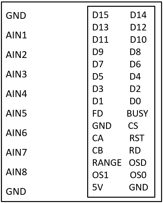
Pin Configuration and Descriptions
The AD7606 comes in a 64-lead LQFP package. Below is a summary of key pins:
| Pin Name | Type | Description |
|---|---|---|
| VDD | Power | Analog power supply (5 V). |
| VSS | Power | Analog ground. |
| VDRIVE | Power | Digital interface supply voltage (1.8 V to 5 V). |
| VINx (x=1-8) | Input | Analog input channels (differential or single-ended). |
| BUSY | Output | Indicates ADC conversion status (active high during conversion). |
| CS | Input | Chip select for SPI interface (active low). |
| RD | Input | Read enable for parallel interface (active low). |
| CONVST | Input | Conversion start signal (active low). |
| DB[15:0] | I/O | Parallel data bus for 16-bit digital output. |
| SCLK | Input | Serial clock for SPI interface. |
| DOUTA/DOUTB | Output | Serial data output channels for SPI interface. |
| RESET | Input | Resets the ADC to its default state (active low). |
For a complete pinout, refer to the official datasheet provided by Analog Devices.
Usage Instructions
How to Use the AD7606 in a Circuit
Power Supply Configuration:
- Connect the analog power supply (VDD) to 5 V and the digital interface supply (VDRIVE) to the desired logic level (1.8 V to 5 V).
- Ensure proper decoupling capacitors are placed close to the power pins to minimize noise.
Input Signal Configuration:
- Connect the analog input signals to the VINx pins. The AD7606 supports both single-ended and differential inputs.
- Select the input voltage range (±10 V or ±5 V) using the RANGE pin or software configuration.
Interface Selection:
- Choose between the parallel or serial (SPI) interface for data communication.
- For SPI, connect SCLK, CS, and DOUTA/DOUTB to the microcontroller or processor.
Start Conversion:
- Trigger a conversion by pulling the CONVST pin low. The BUSY pin will go high during the conversion process.
- Once the BUSY pin goes low, the digital output data is ready to be read.
Read Data:
- For parallel mode, read the 16-bit data from the DB[15:0] pins.
- For SPI mode, clock out the data using SCLK and read it from DOUTA/DOUTB.
Important Considerations and Best Practices
- Use proper grounding techniques to minimize noise and ensure accurate conversions.
- Place anti-aliasing filters on the analog input channels to prevent high-frequency noise from affecting the ADC performance.
- Avoid exceeding the specified input voltage range to prevent damage to the device.
- Use the RESET pin to initialize the ADC to its default state after power-up.
Example: Interfacing AD7606 with Arduino UNO (SPI Mode)
Below is an example Arduino sketch to read data from the AD7606 using SPI:
#include <SPI.h>

// Pin definitions
#define CS_PIN 10  // Chip select pin
#define CONVST_PIN 9  // Conversion start pin
#define BUSY_PIN 8  // Busy status pin

void setup() {
  // Initialize SPI
  SPI.begin();
  SPI.setDataMode(SPI_MODE0);  // SPI mode 0
  SPI.setClockDivider(SPI_CLOCK_DIV16);  // Set SPI clock speed
  pinMode(CS_PIN, OUTPUT);
  pinMode(CONVST_PIN, OUTPUT);
  pinMode(BUSY_PIN, INPUT);

  // Set initial pin states
  digitalWrite(CS_PIN, HIGH);
  digitalWrite(CONVST_PIN, HIGH);

  Serial.begin(9600);  // Initialize serial communication
}

void loop() {
  // Start a conversion
  digitalWrite(CONVST_PIN, LOW);
  delayMicroseconds(1);  // Hold CONVST low for at least 1 µs
  digitalWrite(CONVST_PIN, HIGH);

  // Wait for conversion to complete
  while (digitalRead(BUSY_PIN) == HIGH);

  // Read data from ADC
  digitalWrite(CS_PIN, LOW);  // Select the ADC
  uint16_t adcData = SPI.transfer16(0x0000);  // Read 16-bit data
  digitalWrite(CS_PIN, HIGH);  // Deselect the ADC

  // Print the ADC data
  Serial.println(adcData);

  delay(100);  // Delay for readability
}
Troubleshooting and FAQs
Common Issues and Solutions
No Data Output:
- Ensure the power supply connections (VDD and VDRIVE) are correct and stable.
- Verify that the CONVST pin is being toggled to start a conversion.
Incorrect or Noisy Data:
- Check the input signal levels to ensure they are within the specified range.
- Use proper grounding and shielding to minimize noise interference.
SPI Communication Fails:
- Verify the SPI clock polarity and phase settings (SPI mode 0).
- Ensure the CS pin is properly toggled during data transfer.
Device Not Responding After Power-Up:
- Use the RESET pin to initialize the ADC to its default state.
FAQs
Q: Can the AD7606 handle single-ended inputs?
A: Yes, the AD7606 supports both single-ended and differential input configurations.
Q: What is the maximum sampling rate of the AD7606?
A: The AD7606 supports a maximum sampling rate of 200 kSPS per channel.
Q: How do I select the input voltage range?
A: The input voltage range (±10 V or ±5 V) can be selected using the RANGE pin or through software configuration.
Q: Can I use the AD7606 with a 3.3 V microcontroller?
A: Yes, the AD7606's digital interface (VDRIVE) can operate at 3.3 V, making it compatible with 3.3 V microcontrollers.
For additional details, refer to the official datasheet provided by Analog Devices.