How to Use The Rahul Company: Examples, Pinouts, and Specs
Introduction
The Rahul Company (SUNONX1), manufactured by RBC, is a versatile electronic component designed for a wide range of applications in circuit design and assembly. This component is ideal for both hobbyists and professionals, offering reliable performance and ease of integration into various electronic systems. Its robust design and compatibility with standard microcontrollers make it a popular choice for prototyping and production-level projects.
Explore Projects Built with The Rahul Company
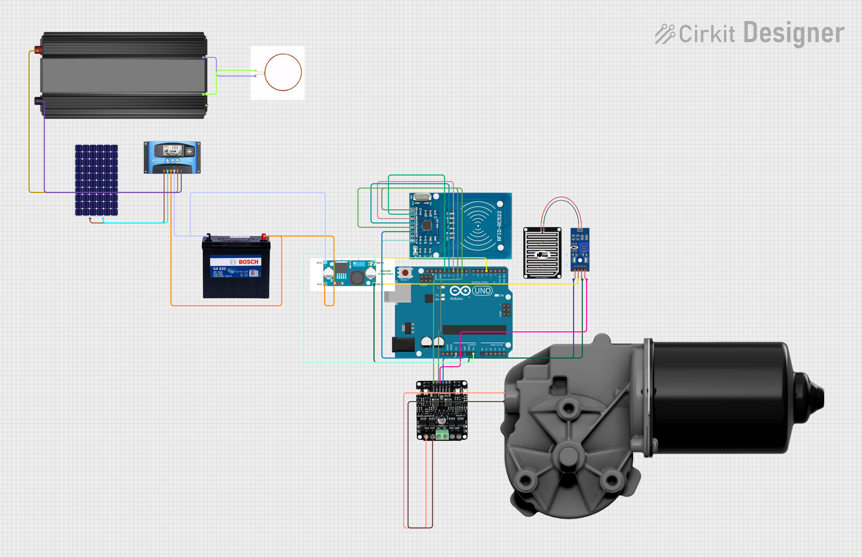
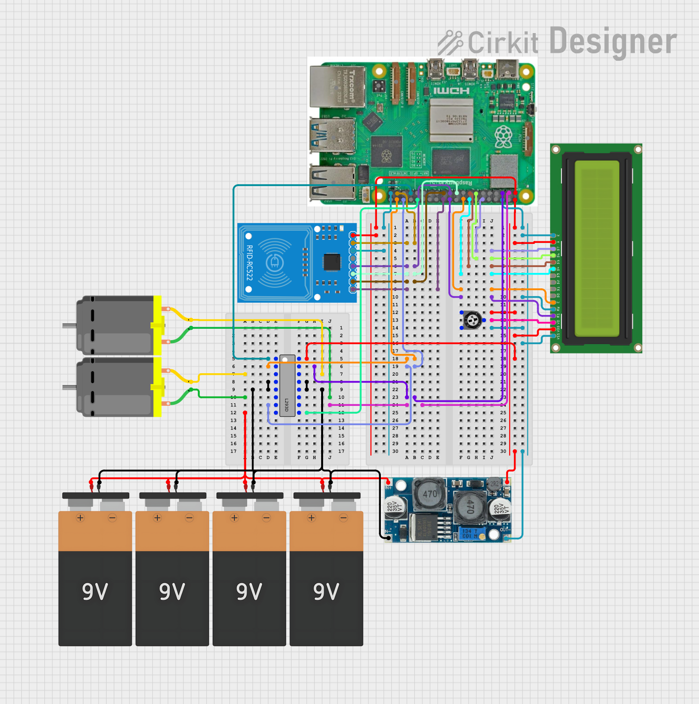
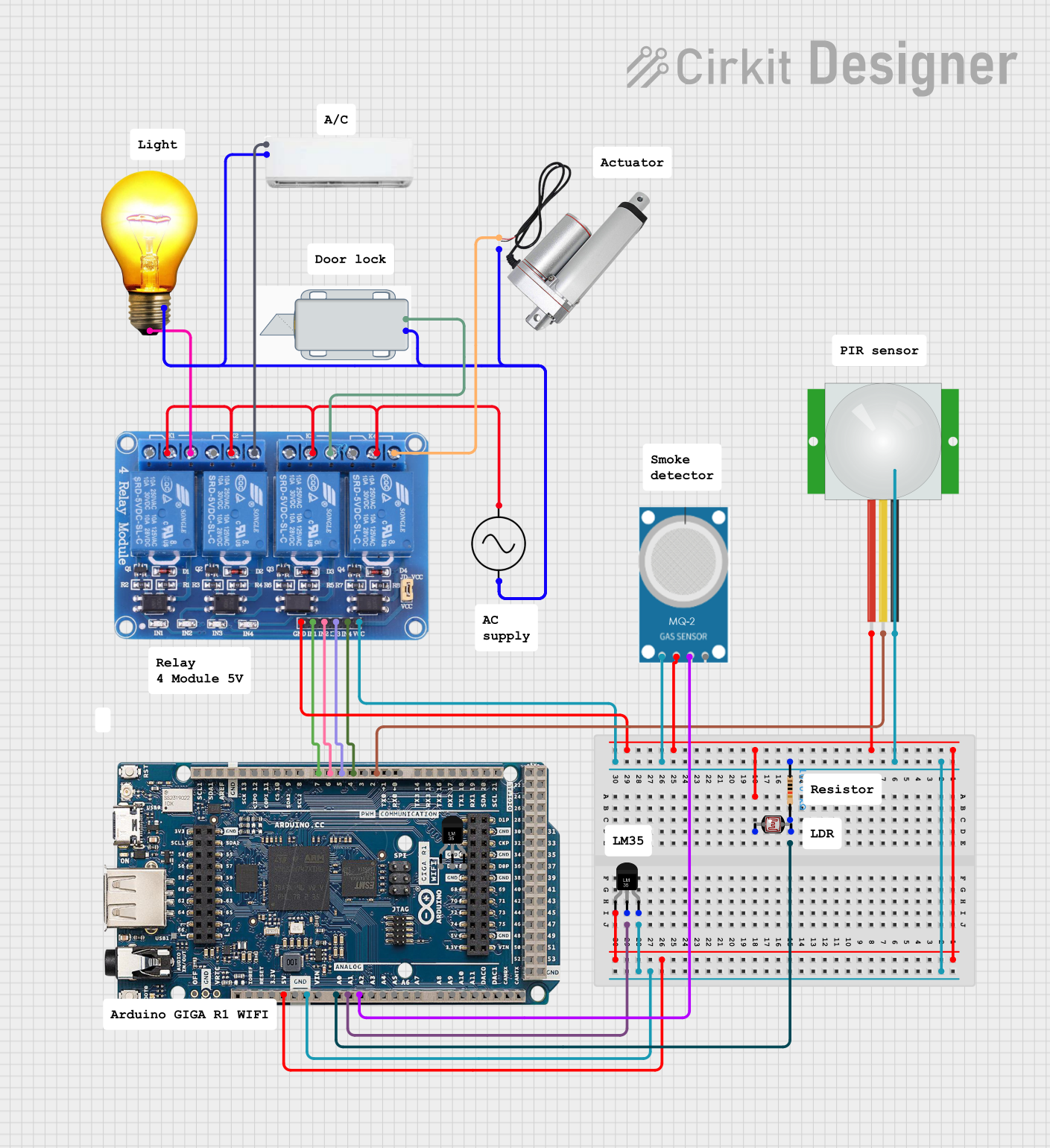
Explore Projects Built with The Rahul Company
Common Applications and Use Cases
- Power regulation and distribution in electronic circuits
- Signal processing and conditioning
- Integration with microcontrollers like Arduino and Raspberry Pi
- Educational projects and prototyping
- Industrial automation and IoT systems
Technical Specifications
The following table outlines the key technical details of the SUNONX1 component:
| Parameter | Value |
|---|---|
| Manufacturer | RBC |
| Part ID | SUNONX1 |
| Operating Voltage | 3.3V to 5V |
| Maximum Current | 500mA |
| Power Rating | 2.5W |
| Operating Temperature | -40°C to +85°C |
| Dimensions | 20mm x 15mm x 5mm |
| Weight | 5 grams |
Pin Configuration and Descriptions
The SUNONX1 has a simple 4-pin configuration, as described in the table below:
| Pin Number | Pin Name | Description |
|---|---|---|
| 1 | VCC | Power supply input (3.3V to 5V) |
| 2 | GND | Ground connection |
| 3 | IN | Input signal for processing or regulation |
| 4 | OUT | Output signal or regulated voltage |
Usage Instructions
How to Use the Component in a Circuit
- Power Supply: Connect the VCC pin to a stable power source within the operating voltage range (3.3V to 5V). Ensure the GND pin is connected to the circuit's ground.
- Input Signal: Feed the input signal to the IN pin. This could be a voltage signal or a digital signal, depending on your application.
- Output Signal: The processed or regulated signal will be available at the OUT pin. Connect this pin to the desired load or circuit.
- Bypass Capacitor: For stable operation, it is recommended to place a 0.1µF ceramic capacitor between VCC and GND.
Important Considerations and Best Practices
- Voltage Limits: Do not exceed the maximum operating voltage of 5V to avoid damaging the component.
- Heat Dissipation: If the component is used near its maximum power rating (2.5W), ensure proper heat dissipation using a heatsink or adequate ventilation.
- Signal Integrity: Use short and thick wires for power connections to minimize voltage drops and noise.
- Testing: Always test the component in a controlled environment before deploying it in critical applications.
Example: Using SUNONX1 with Arduino UNO
Below is an example of how to use the SUNONX1 with an Arduino UNO to process an input signal:
// Example: Using SUNONX1 with Arduino UNO
// This code reads an analog signal, processes it through SUNONX1,
// and outputs the result to a digital pin.

const int inputPin = A0;  // Analog input pin connected to SUNONX1 IN
const int outputPin = 9;  // Digital output pin connected to SUNONX1 OUT

void setup() {
  pinMode(outputPin, OUTPUT);  // Set output pin as OUTPUT
  Serial.begin(9600);         // Initialize serial communication
}

void loop() {
  int sensorValue = analogRead(inputPin);  // Read input signal
  int outputValue = map(sensorValue, 0, 1023, 0, 255);
  // Map input range (0-1023) to output range (0-255)

  analogWrite(outputPin, outputValue);  // Write processed signal to output
  Serial.println(outputValue);          // Print output value for debugging
  delay(100);                           // Delay for stability
}
Troubleshooting and FAQs
Common Issues and Solutions
No Output Signal:
- Cause: Incorrect wiring or loose connections.
- Solution: Double-check all connections, especially VCC, GND, IN, and OUT pins.
Overheating:
- Cause: Exceeding the maximum power rating or insufficient heat dissipation.
- Solution: Reduce the load or add a heatsink to the component.
Signal Distortion:
- Cause: Noise or interference in the input signal.
- Solution: Use shielded cables and add a bypass capacitor between VCC and GND.
Component Not Working:
- Cause: Operating voltage out of range or damaged component.
- Solution: Verify the power supply voltage and replace the component if necessary.
FAQs
Q1: Can the SUNONX1 handle AC signals?
A1: No, the SUNONX1 is designed for DC signals only. Using AC signals may damage the component.
Q2: Is the SUNONX1 compatible with 12V systems?
A2: No, the maximum operating voltage is 5V. For 12V systems, use a voltage regulator to step down the voltage.
Q3: Can I use the SUNONX1 for audio signal processing?
A3: Yes, the SUNONX1 can process low-power audio signals, but ensure the input signal is within the specified voltage range.
Q4: What is the recommended load for the OUT pin?
A4: The recommended load should not exceed 500mA to ensure safe operation.
This concludes the documentation for The Rahul Company (SUNONX1) component. For further assistance, please contact RBC support or refer to the product datasheet.