Cirkit Designer Logo
Cirkit Designer
Your all-in-one circuit design IDE
Home / 
Component Documentation

How to Use Led Module RED: Examples, Pinouts, and Specs

Image of Led Module RED
Cirkit Designer LogoDesign with Led Module RED in Cirkit Designer

Introduction

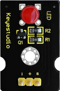
The Keyestudio LED Module RED (Part ID: KS0232) is a compact and versatile light-emitting diode (LED) module that emits bright red light. It is designed for ease of use in a variety of electronic projects, making it ideal for beginners and professionals alike. The module is commonly used as an indicator, in displays, or for decorative lighting purposes. Its simple design allows for quick integration into circuits, and it is compatible with microcontrollers such as Arduino.

Explore Projects Built with Led Module RED

Use Cirkit Designer to design, explore, and prototype these projects online. Some projects support real-time simulation. Click "Open Project" to start designing instantly!
Battery-Powered LED Toggle Switch Circuit
Image of EXP. 7 E: A project utilizing Led Module RED in a practical application
This circuit consists of a red LED, a toggle switch, and a power source. The LED is powered by a 3.7V supply from the MAHIR 1.mini module, and its illumination is controlled by the toggle switch, which connects or disconnects the LED's cathode to ground.
Cirkit Designer LogoOpen Project in Cirkit Designer
Battery-Powered LED Circuit Using MAHIR 1.mini
Image of EXP-1: Led ON Using Direct Battery: A project utilizing Led Module RED in a practical application
This circuit consists of a red LED connected to a MAHIR 1.mini power source. The anode of the LED is connected to the 3.7V pin, and the cathode is connected to the GND pin, allowing the LED to light up when powered.
Cirkit Designer LogoOpen Project in Cirkit Designer
Arduino UNO Controlled LDR and LED Circuit
Image of LDR: A project utilizing Led Module RED in a practical application
This circuit consists of an Arduino UNO connected to an LDR (Light Dependent Resistor) module and a red LED. The LDR module is powered by the Arduino and its analog output (AO) is connected to the Arduino's analog input (A0) for light intensity measurement. The red LED is connected to a digital output (D13) on the Arduino, with its cathode grounded, allowing the Arduino to control the LED based on the LDR's readings or other logic programmed into the Arduino.
Cirkit Designer LogoOpen Project in Cirkit Designer
Battery-Powered LED Control with Pushbutton and Relay
Image of EXP.3 E: A project utilizing Led Module RED in a practical application
This circuit uses a pushbutton to control a 5V relay, which in turn powers a red LED. The MAHIR 1.mini module provides the necessary 3.7V power supply, and the relay switches the LED on and off based on the pushbutton input.
Cirkit Designer LogoOpen Project in Cirkit Designer

Explore Projects Built with Led Module RED

Use Cirkit Designer to design, explore, and prototype these projects online. Some projects support real-time simulation. Click "Open Project" to start designing instantly!
Image of EXP. 7 E: A project utilizing Led Module RED in a practical application
Battery-Powered LED Toggle Switch Circuit
This circuit consists of a red LED, a toggle switch, and a power source. The LED is powered by a 3.7V supply from the MAHIR 1.mini module, and its illumination is controlled by the toggle switch, which connects or disconnects the LED's cathode to ground.
Cirkit Designer LogoOpen Project in Cirkit Designer
Image of EXP-1: Led ON Using Direct Battery: A project utilizing Led Module RED in a practical application
Battery-Powered LED Circuit Using MAHIR 1.mini
This circuit consists of a red LED connected to a MAHIR 1.mini power source. The anode of the LED is connected to the 3.7V pin, and the cathode is connected to the GND pin, allowing the LED to light up when powered.
Cirkit Designer LogoOpen Project in Cirkit Designer
Image of LDR: A project utilizing Led Module RED in a practical application
Arduino UNO Controlled LDR and LED Circuit
This circuit consists of an Arduino UNO connected to an LDR (Light Dependent Resistor) module and a red LED. The LDR module is powered by the Arduino and its analog output (AO) is connected to the Arduino's analog input (A0) for light intensity measurement. The red LED is connected to a digital output (D13) on the Arduino, with its cathode grounded, allowing the Arduino to control the LED based on the LDR's readings or other logic programmed into the Arduino.
Cirkit Designer LogoOpen Project in Cirkit Designer
Image of EXP.3 E: A project utilizing Led Module RED in a practical application
Battery-Powered LED Control with Pushbutton and Relay
This circuit uses a pushbutton to control a 5V relay, which in turn powers a red LED. The MAHIR 1.mini module provides the necessary 3.7V power supply, and the relay switches the LED on and off based on the pushbutton input.
Cirkit Designer LogoOpen Project in Cirkit Designer

Technical Specifications

  • Manufacturer: Keyestudio
  • Part ID: KS0232
  • LED Color: Red
  • Operating Voltage: 3.3V to 5V
  • Current Consumption: ~20mA
  • Dimensions: 18mm x 15mm x 8mm
  • Mounting Type: PCB module with mounting holes
  • Connector Type: 3-pin header (Signal, VCC, GND)

Pin Configuration and Descriptions

The LED Module RED has a 3-pin interface. Below is the pin configuration:

Pin Label Description
1 Signal Input signal to control the LED (active HIGH)
2 VCC Power supply pin (3.3V to 5V)
3 GND Ground connection

Usage Instructions

How to Use the Component in a Circuit

  1. Power Supply: Connect the VCC pin to a 3.3V or 5V power source and the GND pin to the ground of your circuit.
  2. Signal Control: Use the Signal pin to control the LED. When the Signal pin is set HIGH (logic 1), the LED will turn on. When set LOW (logic 0), the LED will turn off.
  3. Resistor Consideration: The module includes an onboard current-limiting resistor, so no external resistor is required for typical use.

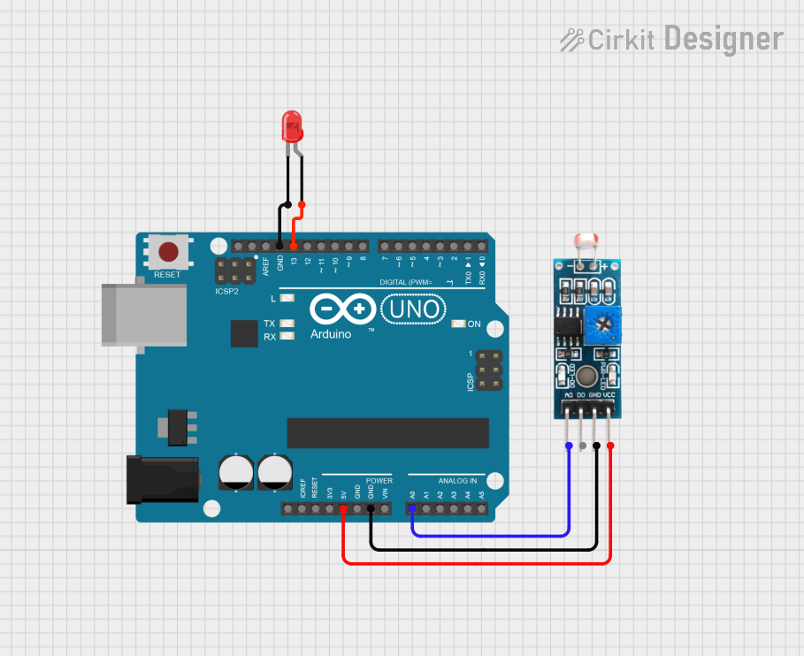
Connecting to an Arduino UNO

The LED Module RED can be easily connected to an Arduino UNO. Follow these steps:

  1. Connect the Signal pin of the module to a digital I/O pin on the Arduino (e.g., pin 9).
  2. Connect the VCC pin to the 5V pin on the Arduino.
  3. Connect the GND pin to the GND pin on the Arduino.

Here is an example Arduino sketch to control the LED:

// Define the pin connected to the LED module
const int ledPin = 9;

void setup() {
  // Set the LED pin as an output
  pinMode(ledPin, OUTPUT);
}

void loop() {
  // Turn the LED on
  digitalWrite(ledPin, HIGH);
  delay(1000); // Wait for 1 second
  
  // Turn the LED off
  digitalWrite(ledPin, LOW);
  delay(1000); // Wait for 1 second
}

Important Considerations and Best Practices

  • Ensure the operating voltage does not exceed 5V to avoid damaging the module.
  • Avoid connecting the Signal pin directly to a high-current source without proper control.
  • If using the module in a high-frequency switching application, consider adding a capacitor to stabilize the power supply.

Troubleshooting and FAQs

Common Issues and Solutions

  1. LED Does Not Light Up:

    • Verify that the VCC and GND pins are correctly connected.
    • Check if the Signal pin is set HIGH in your circuit or code.
    • Ensure the power supply voltage is within the 3.3V to 5V range.
  2. LED Flickers or is Dim:

    • Check for loose connections in the circuit.
    • Ensure the power supply can provide sufficient current (~20mA).
    • If using long wires, consider adding a decoupling capacitor near the module.
  3. Module Overheats:

    • Verify that the operating voltage does not exceed 5V.
    • Ensure the module is not exposed to excessive current.

FAQs

Q: Can I use this module with a 3.3V microcontroller?
A: Yes, the module is compatible with both 3.3V and 5V systems.

Q: Do I need an external resistor for the LED?
A: No, the module includes an onboard current-limiting resistor.

Q: Can I control the brightness of the LED?
A: Yes, you can use PWM (Pulse Width Modulation) on the Signal pin to adjust the brightness.

Q: Is the module suitable for outdoor use?
A: The module is not weatherproof and should be used in indoor or protected environments.

By following this documentation, you can effectively integrate the Keyestudio LED Module RED (KS0232) into your projects for reliable and efficient performance.