How to Use Arduino MKR1000 WIFI: Examples, Pinouts, and Specs
Introduction
The Arduino MKR1000 WIFI is a powerful microcontroller board that combines the functionality of an Arduino with built-in Wi-Fi connectivity, making it an excellent choice for Internet of Things (IoT) applications. It is powered by the SAMD21 Cortex-M0+ 32-bit ARM microcontroller and features an integrated Wi-Fi module (WINC1500) for seamless wireless communication. Additionally, the board includes a battery charging circuit, enabling it to operate in remote or portable applications.
Explore Projects Built with Arduino MKR1000 WIFI
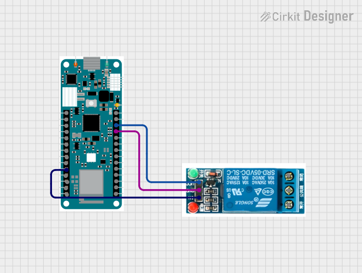
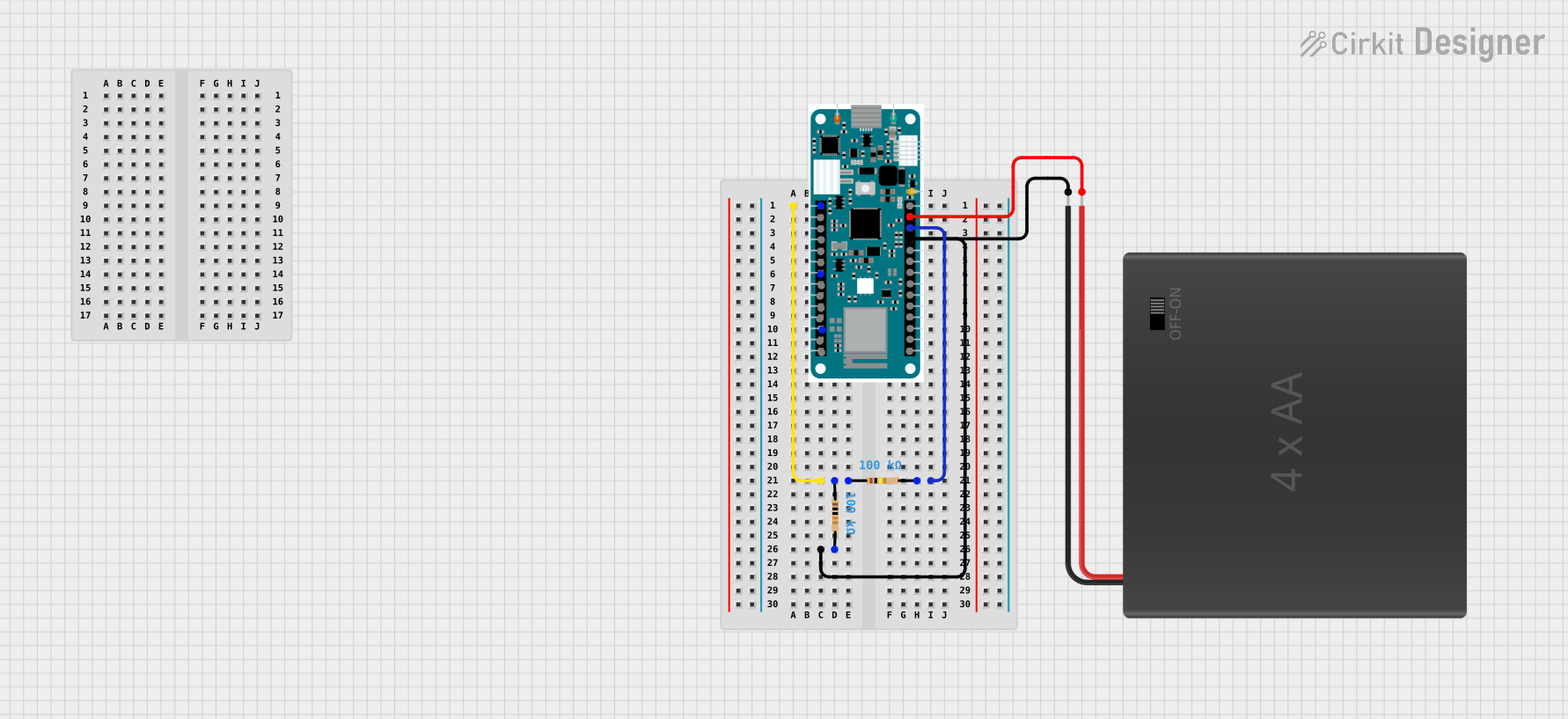

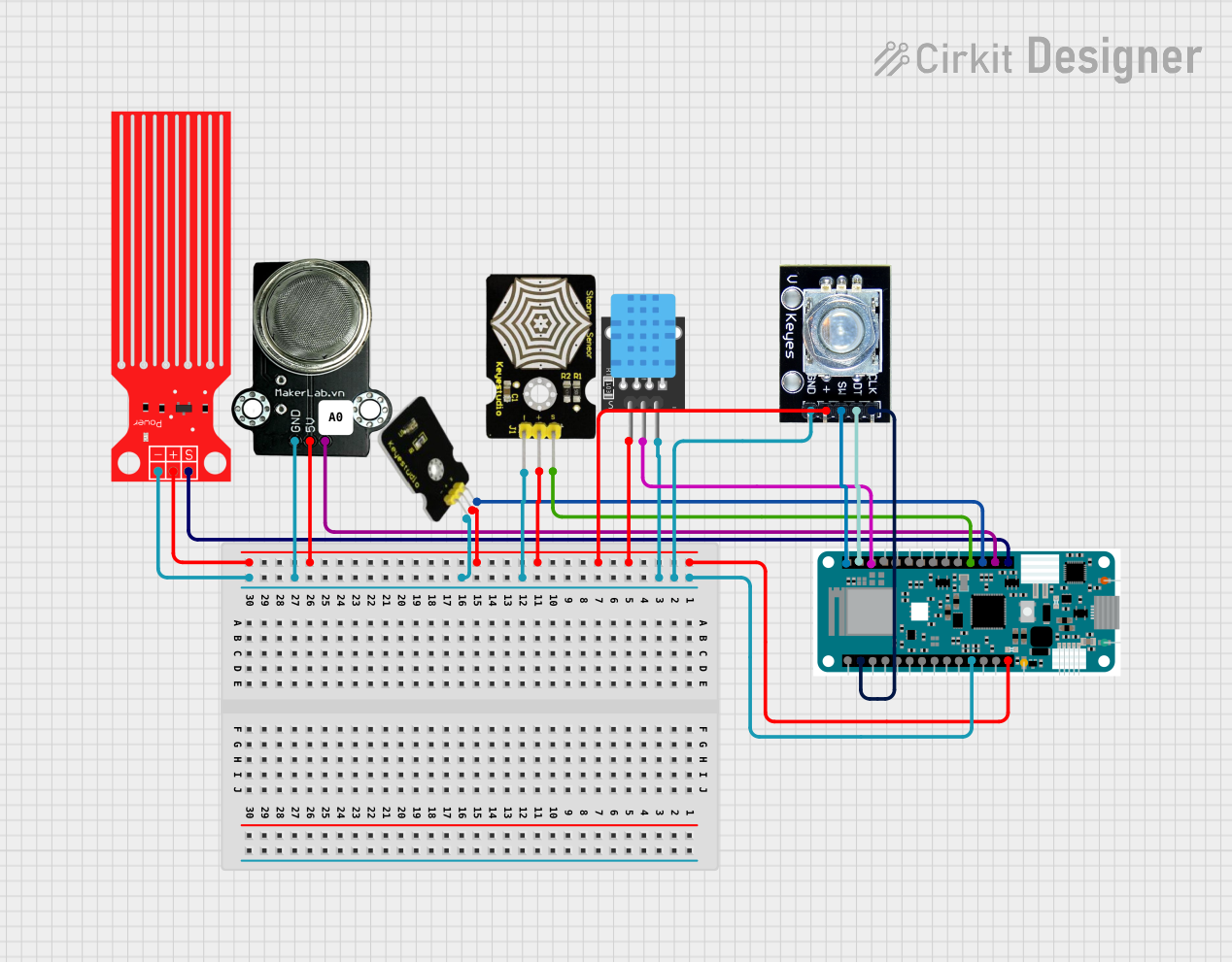
Explore Projects Built with Arduino MKR1000 WIFI
Common Applications and Use Cases
- IoT devices and smart home automation
- Remote sensing and data logging
- Wireless control systems
- Environmental monitoring
- Prototyping connected devices
Technical Specifications
Key Technical Details
| Specification | Value |
|---|---|
| Microcontroller | SAMD21 Cortex-M0+ 32-bit ARM |
| Operating Voltage | 3.3V |
| Input Voltage (VIN) | 5V to 6V |
| Digital I/O Pins | 8 (of which 4 can be used as PWM outputs) |
| Analog Input Pins | 7 |
| Analog Output Pins | 1 (DAC) |
| Flash Memory | 256 KB |
| SRAM | 32 KB |
| Clock Speed | 48 MHz |
| Wi-Fi Module | WINC1500 |
| Battery Connector | Yes (Li-Po, 3.7V) |
| Battery Charging Circuit | Yes |
| Dimensions | 61.5 mm x 25 mm |
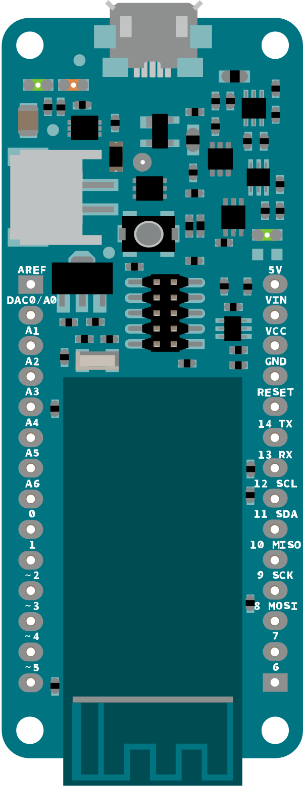
Pin Configuration and Descriptions
| Pin Name | Description |
|---|---|
| VIN | Input voltage pin (5V to 6V) for powering the board. |
| 3.3V | Regulated 3.3V output pin. |
| GND | Ground pin. |
| Digital Pins | D0 to D7: General-purpose digital I/O pins. |
| PWM Pins | D0, D1, D4, D5: Can be used for PWM output. |
| Analog Pins | A0 to A6: Analog input pins. |
| DAC | A0: Can also be used as a digital-to-analog converter (DAC) output. |
| I2C | SDA (D11), SCL (D12): I2C communication pins. |
| SPI | MOSI (D8), MISO (D10), SCK (D9): SPI communication pins. |
| UART | TX (D14), RX (D13): Serial communication pins. |
| RESET | Resets the microcontroller. |
| Battery Pins | JST connector for a 3.7V Li-Po battery. |
Usage Instructions
How to Use the Arduino MKR1000 WIFI in a Circuit
Powering the Board:
- Connect the board to a computer via the micro-USB port for programming and power.
- Alternatively, use the VIN pin (5V to 6V) or a 3.7V Li-Po battery for standalone operation.
Programming the Board:
- Install the Arduino IDE and add the "Arduino SAMD Boards (32-bits ARM Cortex-M0+)" package via the Boards Manager.
- Select "Arduino MKR1000" as the board in the Tools menu.
- Write your code and upload it to the board using the USB connection.
Connecting to Wi-Fi:
- Use the
WiFi101library to connect the MKR1000 to a Wi-Fi network. - Example code for connecting to Wi-Fi is provided below.
- Use the
Interfacing with Sensors and Actuators:
- Use the digital and analog pins to connect sensors and actuators.
- Ensure that all connected components are compatible with the 3.3V logic level of the board.
Important Considerations and Best Practices
- Voltage Levels: The MKR1000 operates at 3.3V. Avoid connecting 5V components directly to its pins.
- Battery Usage: When using a Li-Po battery, ensure it is connected to the dedicated JST connector. The onboard charging circuit will manage the battery.
- Wi-Fi Antenna: The onboard Wi-Fi module has an integrated antenna. Avoid placing the board in metal enclosures or near sources of interference to maintain good signal strength.
- Firmware Updates: Periodically update the firmware of the WINC1500 Wi-Fi module using the
WiFi101library to ensure compatibility and security.
Example Code: Connecting to Wi-Fi
#include <WiFi101.h>

// Replace with your network credentials
const char* ssid = "YourNetworkSSID"; // Your Wi-Fi network name
const char* password = "YourPassword"; // Your Wi-Fi password

void setup() {
  Serial.begin(9600); // Initialize serial communication
  while (!Serial);    // Wait for the serial monitor to open

  Serial.println("Connecting to Wi-Fi...");

  // Attempt to connect to Wi-Fi
  int status = WiFi.begin(ssid, password);

  if (status != WL_CONNECTED) {
    Serial.println("Failed to connect to Wi-Fi");
    while (true); // Halt execution if connection fails
  }

  Serial.println("Connected to Wi-Fi!");
  Serial.print("IP Address: ");
  Serial.println(WiFi.localIP()); // Print the assigned IP address
}

void loop() {
  // Add your main code here
}
Troubleshooting and FAQs
Common Issues and Solutions
The board is not recognized by the computer:
- Ensure the USB cable is functional and supports data transfer.
- Check that the correct board and port are selected in the Arduino IDE.
Wi-Fi connection fails:
- Verify the SSID and password are correct.
- Ensure the Wi-Fi network is operational and within range.
- Update the WINC1500 firmware using the
WiFi101library.
The board overheats:
- Check for short circuits in the connected components.
- Ensure the input voltage does not exceed the recommended range.
Battery is not charging:
- Confirm the battery is a 3.7V Li-Po type.
- Inspect the JST connector for proper connection.
FAQs
Can I use 5V sensors with the MKR1000?
No, the MKR1000 operates at 3.3V logic levels. Use a level shifter for 5V components.What is the maximum range of the Wi-Fi module?
The range depends on environmental factors but is typically around 30 meters indoors.Can I power the board with a USB power bank?
Yes, you can use a USB power bank to power the board via the micro-USB port.How do I update the Wi-Fi module firmware?
Use theWiFi101library's Firmware Updater tool in the Arduino IDE.
This documentation provides a comprehensive guide to using the Arduino MKR1000 WIFI for your IoT projects. Happy prototyping!