Cirkit Designer Logo
Cirkit Designer
Your all-in-one circuit design IDE
Home / 
Component Documentation

How to Use Copernicus II DIP Module: Examples, Pinouts, and Specs

Image of Copernicus II DIP Module
Cirkit Designer LogoDesign with Copernicus II DIP Module in Cirkit Designer

Introduction

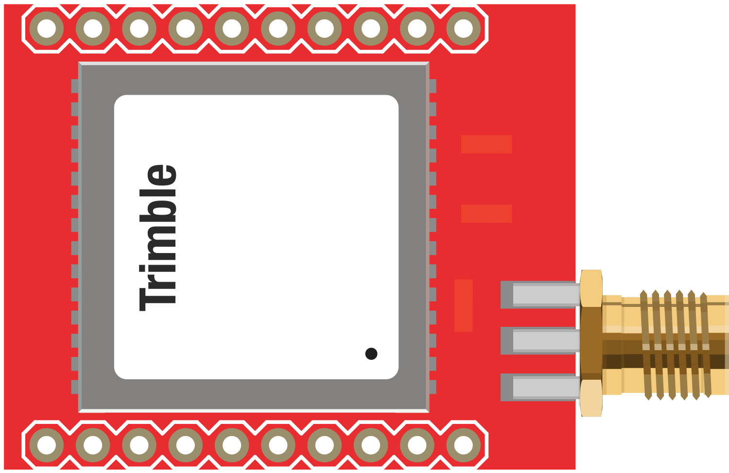
The Copernicus II DIP Module is a compact, high-performance GPS receiver with an integrated antenna designed for a broad spectrum of OEM applications. It is capable of providing precise position and time information. Common applications include asset tracking, navigation devices, time synchronization, and location-based services.

Explore Projects Built with Copernicus II DIP Module

Use Cirkit Designer to design, explore, and prototype these projects online. Some projects support real-time simulation. Click "Open Project" to start designing instantly!
Satellite Compass and Network-Integrated GPS Data Processing System
Image of GPS 시스템 측정 구성도_241016: A project utilizing Copernicus II DIP Module in a practical application
This circuit comprises a satellite compass, a mini PC, two GPS antennas, power supplies, a network switch, media converters, and an atomic rubidium clock. The satellite compass is powered by a triple output DC power supply and interfaces with an RS232 splitter for 1PPS signals. The mini PCs are connected to the USRP B200 devices via USB for data and power, and to media converters via Ethernet, which in turn connect to a network switch using fiber optic links. The antennas are connected to the USRP B200s through RF directional couplers, and the atomic clock provides a 1PPS input to the RS232 splitter.
Cirkit Designer LogoOpen Project in Cirkit Designer
Arduino Nano Based GPS Tracker with GSM Communication and Accelerometer
Image of Circuit Aayush: A project utilizing Copernicus II DIP Module in a practical application
This circuit is designed for communication and location tracking purposes. It features an Arduino Nano interfaced with a SIM800L GSM module for cellular connectivity, a GPS NEO 6M module for obtaining geographical coordinates, and an AITrip ADXL335 GY-61 accelerometer for motion sensing. The LM2596 Step Down Module is used to regulate the power supply to the components.
Cirkit Designer LogoOpen Project in Cirkit Designer
Satellite-Based Timing and Navigation System with SDR and Atomic Clock Synchronization
Image of GPS 시스템 측정 구성도_Confirm: A project utilizing Copernicus II DIP Module in a practical application
This circuit appears to be a complex system involving power supply management, GPS and timing synchronization, and data communication. It includes a SI-TEX G1 Satellite Compass for GPS data, an XHTF1021 Atomic Rubidium Clock for precise timing, and Ettus USRP B200 units for software-defined radio communication. Power is supplied through various SMPS units and distributed via terminal blocks and DC jacks. Data communication is facilitated by Beelink MINI S12 N95 computers, RS232 splitters, and a 1000BASE-T Media Converter for network connectivity. RF Directional Couplers are used to interface antennas with the USRP units, and the entire system is likely contained within cases for protection and organization.
Cirkit Designer LogoOpen Project in Cirkit Designer
ESP8266 and SIM800L Based GPS Tracker with I2C LCD Display and Battery Power
Image of Little Innovator Competition: A project utilizing Copernicus II DIP Module in a practical application
This circuit integrates an ESP8266 NodeMCU microcontroller with a SIM800L GSM module, a GPS NEO 6M module, and a 16x2 I2C LCD display for communication and location tracking. It also includes a pushbutton for user input, a piezo buzzer for audio alerts, and is powered by a 2x 18650 battery pack through an LM2596 step-down module.
Cirkit Designer LogoOpen Project in Cirkit Designer

Explore Projects Built with Copernicus II DIP Module

Use Cirkit Designer to design, explore, and prototype these projects online. Some projects support real-time simulation. Click "Open Project" to start designing instantly!
Image of GPS 시스템 측정 구성도_241016: A project utilizing Copernicus II DIP Module in a practical application
Satellite Compass and Network-Integrated GPS Data Processing System
This circuit comprises a satellite compass, a mini PC, two GPS antennas, power supplies, a network switch, media converters, and an atomic rubidium clock. The satellite compass is powered by a triple output DC power supply and interfaces with an RS232 splitter for 1PPS signals. The mini PCs are connected to the USRP B200 devices via USB for data and power, and to media converters via Ethernet, which in turn connect to a network switch using fiber optic links. The antennas are connected to the USRP B200s through RF directional couplers, and the atomic clock provides a 1PPS input to the RS232 splitter.
Cirkit Designer LogoOpen Project in Cirkit Designer
Image of Circuit Aayush: A project utilizing Copernicus II DIP Module in a practical application
Arduino Nano Based GPS Tracker with GSM Communication and Accelerometer
This circuit is designed for communication and location tracking purposes. It features an Arduino Nano interfaced with a SIM800L GSM module for cellular connectivity, a GPS NEO 6M module for obtaining geographical coordinates, and an AITrip ADXL335 GY-61 accelerometer for motion sensing. The LM2596 Step Down Module is used to regulate the power supply to the components.
Cirkit Designer LogoOpen Project in Cirkit Designer
Image of GPS 시스템 측정 구성도_Confirm: A project utilizing Copernicus II DIP Module in a practical application
Satellite-Based Timing and Navigation System with SDR and Atomic Clock Synchronization
This circuit appears to be a complex system involving power supply management, GPS and timing synchronization, and data communication. It includes a SI-TEX G1 Satellite Compass for GPS data, an XHTF1021 Atomic Rubidium Clock for precise timing, and Ettus USRP B200 units for software-defined radio communication. Power is supplied through various SMPS units and distributed via terminal blocks and DC jacks. Data communication is facilitated by Beelink MINI S12 N95 computers, RS232 splitters, and a 1000BASE-T Media Converter for network connectivity. RF Directional Couplers are used to interface antennas with the USRP units, and the entire system is likely contained within cases for protection and organization.
Cirkit Designer LogoOpen Project in Cirkit Designer
Image of Little Innovator Competition: A project utilizing Copernicus II DIP Module in a practical application
ESP8266 and SIM800L Based GPS Tracker with I2C LCD Display and Battery Power
This circuit integrates an ESP8266 NodeMCU microcontroller with a SIM800L GSM module, a GPS NEO 6M module, and a 16x2 I2C LCD display for communication and location tracking. It also includes a pushbutton for user input, a piezo buzzer for audio alerts, and is powered by a 2x 18650 battery pack through an LM2596 step-down module.
Cirkit Designer LogoOpen Project in Cirkit Designer

Technical Specifications

Key Technical Details

  • Receiver Type: 12-channel, L1 frequency band GPS receiver
  • Update Rate: Up to 10 Hz
  • Sensitivity: -160 dBm tracking, -142 dBm acquisition
  • Time to First Fix: 29 seconds (cold start), 1 second (hot start)
  • Operating Voltage: 2.7V to 3.6V
  • Power Consumption: 44 mA at 3.3V (typical)
  • Operating Temperature: -40°C to +85°C
  • Dimensions: 19.2 mm x 19.2 mm x 2.5 mm

Pin Configuration and Descriptions

Pin Number Name Description
1 VCC Power supply input (2.7V to 3.6V)
2 GND Ground connection
3 TX Serial transmit output (TTL level)
4 RX Serial receive input (TTL level)
5 ON/OFF Power control pin (pull low to power down)
6 RESET Module reset input (active low)
7 PPS Pulse per second output
8 NC No connection (reserved for future use)

Usage Instructions

Integration into a Circuit

  1. Power Supply: Connect the VCC pin to a clean, regulated 3.3V power source. Ensure that the power supply can deliver sufficient current for the module's operation.
  2. Grounding: Connect the GND pin to the system ground.
  3. Serial Communication: Connect the TX and RX pins to a microcontroller or another serial device for data communication. Remember to cross-connect TX to RX and RX to TX.
  4. Power Control: If you wish to control the power state of the module, connect the ON/OFF pin to a digital output on your microcontroller.
  5. Reset: The RESET pin can be connected to a microcontroller or left unconnected if not used.
  6. PPS Output: The PPS pin outputs a pulse per second, which can be used for precise timing applications.

Best Practices

  • Ensure that the antenna has a clear view of the sky for optimal performance.
  • Avoid placing the module near sources of RF interference.
  • Use short and direct connections to the power supply to minimize voltage drops.
  • Implement proper decoupling capacitors close to the module's power supply pins to filter out noise.

Example Code for Arduino UNO

#include <SoftwareSerial.h>

SoftwareSerial gpsSerial(10, 11); // RX, TX

void setup() {
  // Start the serial communication with the host computer
  Serial.begin(9600);
  while (!Serial) {
    ; // Wait for serial port to connect.
  }

  // Start communication with the GPS module
  gpsSerial.begin(4800);
  Serial.println("GPS Module Copernicus II DIP started");
}

void loop() {
  // Check if data is available from the GPS module
  if (gpsSerial.available()) {
    // Forward the data from the GPS module to the host computer
    Serial.write(gpsSerial.read());
  }

  // Check if data is available from the host computer
  if (Serial.available()) {
    // Forward the data from the host computer to the GPS module
    gpsSerial.write(Serial.read());
  }
}

Troubleshooting and FAQs

Common Issues

  • No GPS Fix: Ensure the antenna has a clear view of the sky. Check for any obstructions or interference sources.
  • No Data Output: Verify the baud rate and wiring connections between the GPS module and the microcontroller.
  • Intermittent Signal: Check for loose connections and ensure the power supply is stable and within the specified voltage range.

Solutions and Tips

  • Power Issues: Use a multimeter to check the voltage at the VCC pin. It should be between 2.7V and 3.6V.
  • Signal Quality: Place the module away from tall buildings, trees, and other obstructions.
  • Data Communication: Ensure that the serial communication parameters (baud rate, data bits, etc.) match between the GPS module and the microcontroller.

FAQs

Q: Can I use an external antenna with the Copernicus II DIP Module? A: The module comes with an integrated antenna, but it also supports an external antenna if needed.

Q: What is the default baud rate for the Copernicus II DIP Module? A: The default baud rate is 4800 bps.

Q: How can I change the update rate of the GPS module? A: The update rate can be configured using proprietary configuration commands. Refer to the module's datasheet for detailed instructions.

Q: Is the Copernicus II DIP Module waterproof? A: The module itself is not waterproof. It should be housed in a waterproof enclosure if used in outdoor environments.

For further assistance, consult the Copernicus II DIP Module datasheet or contact technical support.