Cirkit Designer Logo
Cirkit Designer
Your all-in-one circuit design IDE
Home / 
Component Documentation

How to Use ESP32-C3-DevKitM-1: Examples, Pinouts, and Specs

Image of ESP32-C3-DevKitM-1
Cirkit Designer LogoDesign with ESP32-C3-DevKitM-1 in Cirkit Designer

Introduction

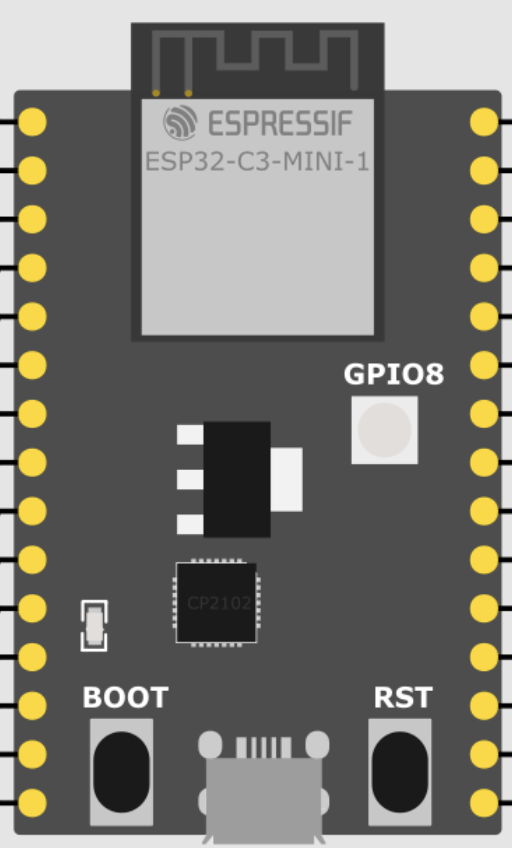
The ESP32-C3-DevKitM-1 is a small-sized, feature-rich development board based on the ESP32-C3 RISC-V microcontroller. This board is specifically designed for Internet of Things (IoT) applications, offering both Wi-Fi and Bluetooth Low Energy (BLE) connectivity. It is an ideal choice for smart home devices, industrial automation, wearable electronics, and other wireless control systems.

Explore Projects Built with ESP32-C3-DevKitM-1

Use Cirkit Designer to design, explore, and prototype these projects online. Some projects support real-time simulation. Click "Open Project" to start designing instantly!
ESP32-Based Environmental Monitoring and Alert System with Solar Charging
Image of mark: A project utilizing ESP32-C3-DevKitM-1 in a practical application
This circuit features an ESP32 Devkit V1 microcontroller connected to various sensors and modules for monitoring and communication purposes. It includes an MQ-2 gas sensor and a DHT11 temperature and humidity sensor, both interfaced with the ESP32 for environmental data collection. The circuit is powered by a 12V battery, regulated to 5V by step-down converters, and includes a solar charge controller connected to a solar panel for battery charging, a UPS module for power management, and a SIM900A module for GSM communication. Additionally, there is a WS2812 RGB LED strip for visual feedback and a piezo buzzer for audio alerts, both controlled by the ESP32.
Cirkit Designer LogoOpen Project in Cirkit Designer
ESP32 Devkit V1 and OLED Display Bitmap Viewer
Image of Esp32_monochromeimage: A project utilizing ESP32-C3-DevKitM-1 in a practical application
This circuit consists of an ESP32 Devkit V1 microcontroller connected to a 1.3" OLED display via I2C communication. The ESP32 initializes the OLED display and renders a predefined bitmap image on it.
Cirkit Designer LogoOpen Project in Cirkit Designer
ESP32-Based GPS Tracker with SD Card Logging and Barometric Sensor
Image of gps projekt circuit: A project utilizing ESP32-C3-DevKitM-1 in a practical application
This circuit features an ESP32 Wroom Dev Kit as the main microcontroller, interfaced with an MPL3115A2 sensor for pressure and temperature readings, and a Neo 6M GPS module for location tracking. The ESP32 is also connected to an SD card reader for data logging purposes. A voltage regulator is used to step down the USB power supply to 3.3V, which powers the ESP32, the sensor, and the SD card reader.
Cirkit Designer LogoOpen Project in Cirkit Designer
ESP32-Based Environmental Monitoring and Alert System with Solar Charging
Image of Schematic: A project utilizing ESP32-C3-DevKitM-1 in a practical application
This circuit features an ESP32 Devkit V1 microcontroller connected to various sensors and devices, including a DHT11 temperature and humidity sensor, an MQ-2 gas sensor, and a WS2812 RGB LED strip. The ESP32 controls the LED strip and processes sensor readings, while a SIM900A module provides cellular communication capabilities. Power management is handled by a UPS module fed by a 12V battery charged via a solar panel and charge controller, with voltage regulation provided by step-down converters. Additionally, a piezo buzzer is included for audible alerts, and the system's safety is ensured by a circuit breaker connected to a switching power supply for AC to DC conversion.
Cirkit Designer LogoOpen Project in Cirkit Designer

Explore Projects Built with ESP32-C3-DevKitM-1

Use Cirkit Designer to design, explore, and prototype these projects online. Some projects support real-time simulation. Click "Open Project" to start designing instantly!
Image of mark: A project utilizing ESP32-C3-DevKitM-1 in a practical application
ESP32-Based Environmental Monitoring and Alert System with Solar Charging
This circuit features an ESP32 Devkit V1 microcontroller connected to various sensors and modules for monitoring and communication purposes. It includes an MQ-2 gas sensor and a DHT11 temperature and humidity sensor, both interfaced with the ESP32 for environmental data collection. The circuit is powered by a 12V battery, regulated to 5V by step-down converters, and includes a solar charge controller connected to a solar panel for battery charging, a UPS module for power management, and a SIM900A module for GSM communication. Additionally, there is a WS2812 RGB LED strip for visual feedback and a piezo buzzer for audio alerts, both controlled by the ESP32.
Cirkit Designer LogoOpen Project in Cirkit Designer
Image of Esp32_monochromeimage: A project utilizing ESP32-C3-DevKitM-1 in a practical application
ESP32 Devkit V1 and OLED Display Bitmap Viewer
This circuit consists of an ESP32 Devkit V1 microcontroller connected to a 1.3" OLED display via I2C communication. The ESP32 initializes the OLED display and renders a predefined bitmap image on it.
Cirkit Designer LogoOpen Project in Cirkit Designer
Image of gps projekt circuit: A project utilizing ESP32-C3-DevKitM-1 in a practical application
ESP32-Based GPS Tracker with SD Card Logging and Barometric Sensor
This circuit features an ESP32 Wroom Dev Kit as the main microcontroller, interfaced with an MPL3115A2 sensor for pressure and temperature readings, and a Neo 6M GPS module for location tracking. The ESP32 is also connected to an SD card reader for data logging purposes. A voltage regulator is used to step down the USB power supply to 3.3V, which powers the ESP32, the sensor, and the SD card reader.
Cirkit Designer LogoOpen Project in Cirkit Designer
Image of Schematic: A project utilizing ESP32-C3-DevKitM-1 in a practical application
ESP32-Based Environmental Monitoring and Alert System with Solar Charging
This circuit features an ESP32 Devkit V1 microcontroller connected to various sensors and devices, including a DHT11 temperature and humidity sensor, an MQ-2 gas sensor, and a WS2812 RGB LED strip. The ESP32 controls the LED strip and processes sensor readings, while a SIM900A module provides cellular communication capabilities. Power management is handled by a UPS module fed by a 12V battery charged via a solar panel and charge controller, with voltage regulation provided by step-down converters. Additionally, a piezo buzzer is included for audible alerts, and the system's safety is ensured by a circuit breaker connected to a switching power supply for AC to DC conversion.
Cirkit Designer LogoOpen Project in Cirkit Designer

Common Applications and Use Cases

  • Smart home devices (lighting, security systems, thermostats)
  • Industrial automation and monitoring
  • Wearable electronics
  • Wireless sensor networks
  • IoT prototyping and development

Technical Specifications

Key Technical Details

  • Microcontroller: ESP32-C3 RISC-V single-core 32-bit LX6 microprocessor
  • Operating Voltage: 3.3V
  • Input Voltage: 5V via micro-USB port
  • Current Consumption: ~10 mA (idle), up to 500 mA (Wi-Fi transmission)
  • Flash Memory: 4 MB
  • SRAM: 400 KB
  • Wi-Fi: 802.11 b/g/n (2.4 GHz)
  • Bluetooth: v5.0 with BLE support
  • GPIO Pins: 22
  • UARTs: 2
  • SPIs: 2
  • I2Cs: 1
  • ADC Channels: 6 (12-bit resolution)
  • DAC Channels: 2 (8-bit resolution)
  • PWM Channels: 8
  • Temperature Sensor: On-chip sensor

Pin Configuration and Descriptions

Pin Number Function Description
1 3V3 3.3V power supply
2 GND Ground
3 EN Reset pin, active low
4 IO0 General-purpose input/output, bootstrapping
... ... ...
n IO21 General-purpose input/output

Note: This is a simplified representation. Please refer to the official datasheet for the complete pinout.

Usage Instructions

How to Use the Component in a Circuit

  1. Powering the Board:

    • Connect the micro-USB port to a 5V USB power source.
    • Ensure that the power supply can provide sufficient current for the board and any connected peripherals.
  2. Connecting to Wi-Fi:

    • Use the provided libraries to connect the ESP32-C3 to a Wi-Fi network.
    • Ensure that the antenna is positioned for optimal signal strength.
  3. Programming the Board:

    • Install the required drivers and the ESP-IDF or Arduino IDE on your computer.
    • Use a micro-USB cable to connect the board to your computer.
    • Select the appropriate board and port in your IDE.
  4. Interfacing with GPIO Pins:

    • Connect sensors, actuators, or other peripherals to the GPIO pins.
    • Configure the pins as input or output according to your needs.

Important Considerations and Best Practices

  • Always disconnect the board from power before making or altering connections.
  • Use a logic level converter if interfacing with components that operate at a different voltage.
  • Avoid drawing more current from the GPIO pins than the specified limit.
  • Ensure proper static discharge precautions when handling the board.

Troubleshooting and FAQs

Common Issues Users Might Face

  • Board not powering up: Check the USB cable and power source. Ensure the EN pin is not being pulled low inadvertently.
  • Cannot connect to Wi-Fi: Verify the network credentials and signal strength. Check if the antenna is properly connected and positioned.
  • Problems with uploading code: Ensure the correct drivers are installed, and the board is selected in the IDE. Check the USB cable and port.

Solutions and Tips for Troubleshooting

  • If the board does not power up, try a different USB cable and power source.
  • For Wi-Fi issues, try moving the board closer to the router or using an external antenna if available.
  • If you have trouble uploading code, double-check the boot mode and ensure that GPIO0 is pulled low during a reset to enter the bootloader.

Example Code for Arduino UNO

#include <WiFi.h>

// Replace with your network credentials
const char* ssid = "your_SSID";
const char* password = "your_PASSWORD";

void setup() {
  Serial.begin(115200);
  
  // Connect to Wi-Fi
  WiFi.begin(ssid, password);
  while (WiFi.status() != WL_CONNECTED) {
    delay(500);
    Serial.println("Connecting to WiFi...");
  }
  Serial.println("Connected to WiFi");
}

void loop() {
  // Your code here
}

Note: This example demonstrates how to connect the ESP32-C3-DevKitM-1 to a Wi-Fi network. Ensure that you have the ESP32-C3 board support installed in the Arduino IDE before uploading this sketch.