Cirkit Designer Logo
Cirkit Designer
Your all-in-one circuit design IDE
Home / 
Component Documentation

How to Use cp2112: Examples, Pinouts, and Specs

Image of cp2112
Cirkit Designer LogoDesign with cp2112 in Cirkit Designer

Introduction

The CP2112 is a USB to I2C bridge controller manufactured by Amazon, with the part ID CP2112. This versatile component enables seamless communication between USB devices and I2C peripherals, making it an essential tool for applications requiring USB-to-I2C conversion. The CP2112 features a built-in oscillator, supports multiple I2C speeds, and can be configured via USB for a wide range of use cases.

Explore Projects Built with cp2112

Use Cirkit Designer to design, explore, and prototype these projects online. Some projects support real-time simulation. Click "Open Project" to start designing instantly!
Battery-Powered Raspberry Pi Pico GPS Tracker with Sensor Integration
Image of Copy of CanSet v1: A project utilizing cp2112 in a practical application
This circuit is a data acquisition and communication system powered by a LiPoly battery and managed by a Raspberry Pi Pico. It includes sensors (BMP280, MPU9250) for environmental data, a GPS module for location tracking, an SD card for data storage, and a WLR089-CanSAT for wireless communication. The TP4056 module handles battery charging, and a toggle switch controls power distribution.
Cirkit Designer LogoOpen Project in Cirkit Designer
Cellular-Enabled IoT Device with Real-Time Clock and Power Management
Image of LRCM PHASE 2 BASIC: A project utilizing cp2112 in a practical application
This circuit features a LilyGo-SIM7000G module for cellular communication and GPS functionality, interfaced with an RTC DS3231 for real-time clock capabilities. It includes voltage sensing through two voltage sensor modules, and uses an 8-channel opto-coupler for isolating different parts of the circuit. Power management is handled by a buck converter connected to a DC power source and batteries, with a fuse for protection and a rocker switch for on/off control. Additionally, there's an LED for indication purposes.
Cirkit Designer LogoOpen Project in Cirkit Designer
ESP32-Based Automatic Passenger Counter and Temperature Sensor with Wi-Fi Connectivity
Image of Embedded Circuit: A project utilizing cp2112 in a practical application
This circuit is an automatic passenger counter and temperature sensor system powered by a solar charger. It uses an ESP32 microcontroller to interface with two capacitive proximity sensors for counting passengers and a DHT22 sensor for monitoring temperature and humidity, with data being sent to a Blynk mobile app and Google Sheets for real-time tracking and logging.
Cirkit Designer LogoOpen Project in Cirkit Designer
Arduino Mega 2560 Based Security System with Fingerprint Authentication and SMS Alerts
Image of Door security system: A project utilizing cp2112 in a practical application
This circuit features an Arduino Mega 2560 microcontroller interfaced with a SIM800L GSM module, two fingerprint scanners, an I2C LCD display, an IR sensor, and a piezo buzzer. Power management is handled by a PowerBoost 1000 Basic Pad USB, a TP4056 charging module, and a Li-ion 18650 battery, with an option to use a Mini AC-DC 110V-230V to 5V 700mA module for direct power supply. The primary functionality appears to be a security system with GSM communication capabilities, biometric access control, and visual/audible feedback.
Cirkit Designer LogoOpen Project in Cirkit Designer

Explore Projects Built with cp2112

Use Cirkit Designer to design, explore, and prototype these projects online. Some projects support real-time simulation. Click "Open Project" to start designing instantly!
Image of Copy of CanSet v1: A project utilizing cp2112 in a practical application
Battery-Powered Raspberry Pi Pico GPS Tracker with Sensor Integration
This circuit is a data acquisition and communication system powered by a LiPoly battery and managed by a Raspberry Pi Pico. It includes sensors (BMP280, MPU9250) for environmental data, a GPS module for location tracking, an SD card for data storage, and a WLR089-CanSAT for wireless communication. The TP4056 module handles battery charging, and a toggle switch controls power distribution.
Cirkit Designer LogoOpen Project in Cirkit Designer
Image of LRCM PHASE 2 BASIC: A project utilizing cp2112 in a practical application
Cellular-Enabled IoT Device with Real-Time Clock and Power Management
This circuit features a LilyGo-SIM7000G module for cellular communication and GPS functionality, interfaced with an RTC DS3231 for real-time clock capabilities. It includes voltage sensing through two voltage sensor modules, and uses an 8-channel opto-coupler for isolating different parts of the circuit. Power management is handled by a buck converter connected to a DC power source and batteries, with a fuse for protection and a rocker switch for on/off control. Additionally, there's an LED for indication purposes.
Cirkit Designer LogoOpen Project in Cirkit Designer
Image of Embedded Circuit: A project utilizing cp2112 in a practical application
ESP32-Based Automatic Passenger Counter and Temperature Sensor with Wi-Fi Connectivity
This circuit is an automatic passenger counter and temperature sensor system powered by a solar charger. It uses an ESP32 microcontroller to interface with two capacitive proximity sensors for counting passengers and a DHT22 sensor for monitoring temperature and humidity, with data being sent to a Blynk mobile app and Google Sheets for real-time tracking and logging.
Cirkit Designer LogoOpen Project in Cirkit Designer
Image of Door security system: A project utilizing cp2112 in a practical application
Arduino Mega 2560 Based Security System with Fingerprint Authentication and SMS Alerts
This circuit features an Arduino Mega 2560 microcontroller interfaced with a SIM800L GSM module, two fingerprint scanners, an I2C LCD display, an IR sensor, and a piezo buzzer. Power management is handled by a PowerBoost 1000 Basic Pad USB, a TP4056 charging module, and a Li-ion 18650 battery, with an option to use a Mini AC-DC 110V-230V to 5V 700mA module for direct power supply. The primary functionality appears to be a security system with GSM communication capabilities, biometric access control, and visual/audible feedback.
Cirkit Designer LogoOpen Project in Cirkit Designer

Common Applications and Use Cases

  • USB-to-I2C communication for embedded systems
  • Debugging and testing I2C devices
  • Interfacing USB devices with sensors, EEPROMs, or other I2C peripherals
  • Prototyping and development of I2C-based systems
  • Industrial automation and control systems

Technical Specifications

The CP2112 is designed to provide reliable and efficient USB-to-I2C communication. Below are its key technical specifications:

Parameter Value
USB Interface USB 2.0 Full-Speed
I2C Interface Master Mode
I2C Clock Speeds 100 kHz, 400 kHz, 1 MHz
Operating Voltage 3.3 V (core)
GPIO Pins 8 configurable GPIO pins
Built-in Oscillator Yes
Operating Temperature Range -40°C to +85°C
Package Type QFN-24

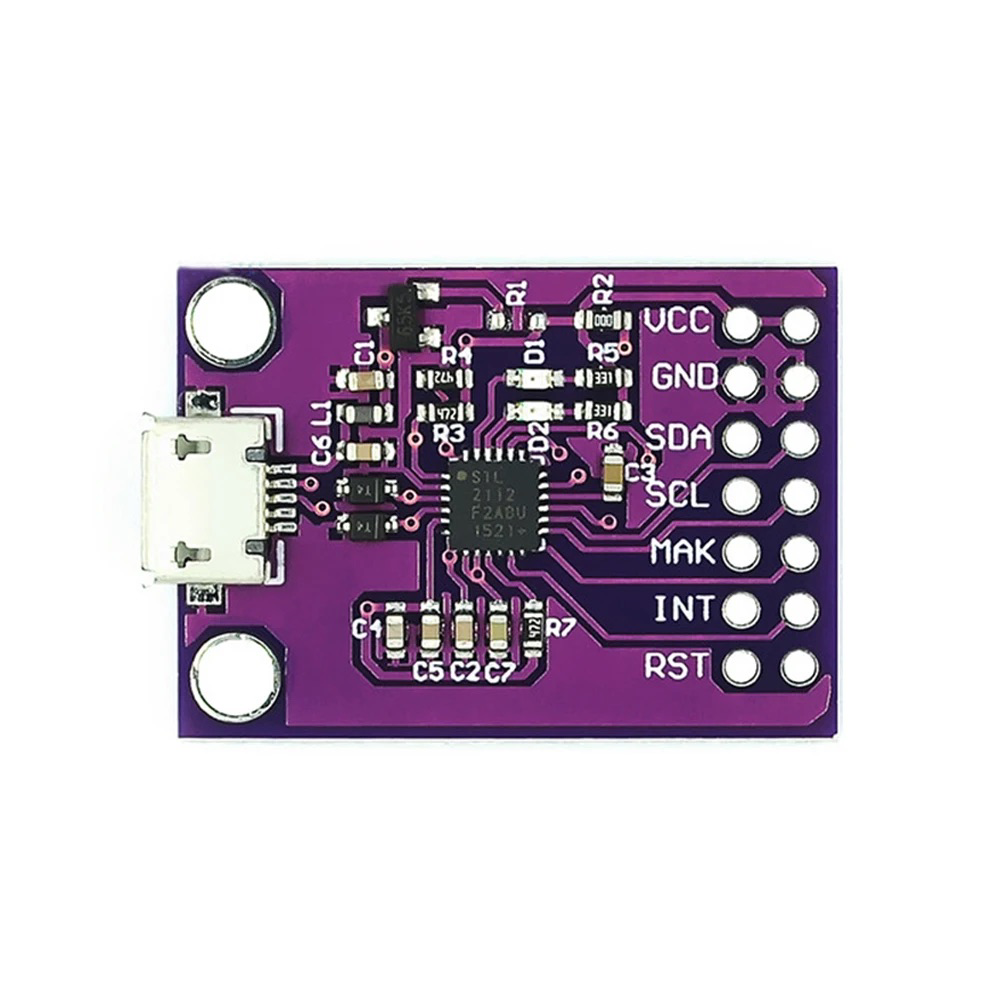
Pin Configuration and Descriptions

The CP2112 comes in a 24-pin QFN package. Below is the pin configuration and description:

Pin Number Pin Name Description
1 VDD Power supply input (3.3 V)
2 GND Ground
3 SDA I2C data line
4 SCL I2C clock line
5-12 GPIO.0-7 Configurable GPIO pins
13 USB_DP USB data positive
14 USB_DM USB data negative
15 RSTb Reset (active low)
16-24 NC No connection

Usage Instructions

The CP2112 is straightforward to use in a circuit, thanks to its USB and I2C interfaces. Below are the steps and best practices for using the CP2112:

Connecting the CP2112

  1. Power Supply: Connect the VDD pin to a 3.3 V power source and the GND pin to ground.
  2. USB Interface: Connect the USB_DP and USB_DM pins to the USB data lines of your host device.
  3. I2C Interface: Connect the SDA and SCL pins to the corresponding I2C lines of your peripheral device.
  4. GPIO Pins: Configure the GPIO pins as needed for your application (e.g., input, output, or special functions).

Important Considerations

  • Pull-Up Resistors: Ensure that the SDA and SCL lines have appropriate pull-up resistors (typically 4.7 kΩ or 10 kΩ).
  • I2C Speed: Configure the I2C clock speed (100 kHz, 400 kHz, or 1 MHz) based on the requirements of your peripheral device.
  • Driver Installation: Install the necessary USB drivers for the CP2112 on your host device. These drivers are typically available from the manufacturer's website.
  • Configuration Utility: Use the CP2112 configuration utility to set up GPIO pins, I2C parameters, and other settings.

Example: Using CP2112 with Arduino UNO

Although the CP2112 is not directly programmable like an Arduino, it can be used alongside an Arduino UNO to interface with I2C peripherals. Below is an example Arduino sketch for communicating with an I2C device:

#include <Wire.h> // Include the Wire library for I2C communication

#define I2C_ADDRESS 0x40 // Replace with the I2C address of your device

void setup() {
  Wire.begin(); // Initialize the I2C bus
  Serial.begin(9600); // Initialize serial communication for debugging
  Serial.println("CP2112 I2C Communication Example");
}

void loop() {
  Wire.beginTransmission(I2C_ADDRESS); // Start communication with the I2C device
  Wire.write(0x01); // Send a command or data byte (replace with your data)
  if (Wire.endTransmission() == 0) { // Check if the transmission was successful
    Serial.println("Data sent successfully!");
  } else {
    Serial.println("Error: Transmission failed.");
  }
  delay(1000); // Wait for 1 second before sending the next command
}

Troubleshooting and FAQs

Common Issues and Solutions

  1. Issue: The CP2112 is not recognized by the host device.

    • Solution: Ensure that the USB drivers are correctly installed. Check the USB connection and verify that the CP2112 is powered.
  2. Issue: I2C communication is not working.

    • Solution: Verify the pull-up resistors on the SDA and SCL lines. Check the I2C address of the peripheral device and ensure it matches the address used in your code.
  3. Issue: GPIO pins are not functioning as expected.

    • Solution: Use the CP2112 configuration utility to ensure the GPIO pins are correctly configured for your application.

FAQs

  • Q: Can the CP2112 operate at 5 V?

    • A: No, the CP2112 operates at 3.3 V. Ensure that all connected devices are compatible with this voltage level.
  • Q: How do I change the I2C clock speed?

    • A: Use the CP2112 configuration utility to set the desired I2C clock speed.
  • Q: Is the CP2112 compatible with Linux?

    • A: Yes, the CP2112 is compatible with Linux. Ensure that the appropriate drivers are installed.

By following this documentation, you can effectively integrate the CP2112 into your projects and troubleshoot common issues.