Cirkit Designer Logo
Cirkit Designer
Your all-in-one circuit design IDE
Home / 
Component Documentation

How to Use relay esp01s: Examples, Pinouts, and Specs

Image of relay esp01s
Cirkit Designer LogoDesign with relay esp01s in Cirkit Designer

Introduction

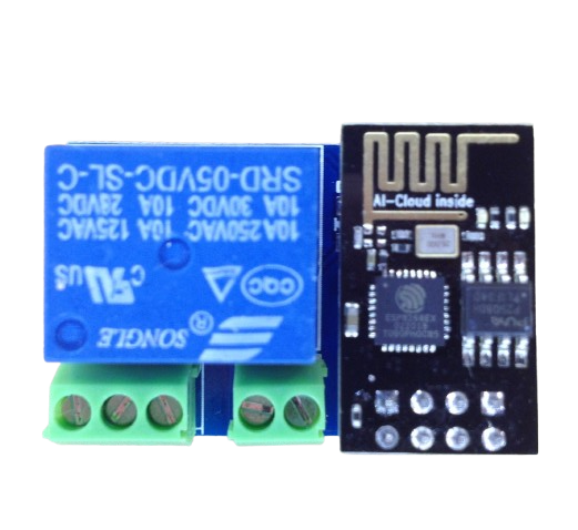
The Relay ESP01S is a compact and versatile relay module designed to work seamlessly with the ESP-01S Wi-Fi module. Manufactured by ESP, this component allows users to control high-voltage devices remotely via Wi-Fi. It is widely used in IoT applications, home automation systems, and smart appliances due to its ease of integration and reliable performance.

Explore Projects Built with relay esp01s

Use Cirkit Designer to design, explore, and prototype these projects online. Some projects support real-time simulation. Click "Open Project" to start designing instantly!
Wi-Fi Controlled Relay Module with ESP8266 and MCP23017
Image of smart home: A project utilizing relay esp01s in a practical application
This circuit is a WiFi-enabled relay control system using an ESP8266-01 module and an MCP23017 I/O expander. The ESP8266 communicates with the MCP23017 via I2C to control an 8-channel relay module based on the state of 8 rocker switches, allowing for remote and manual control of connected devices.
Cirkit Designer LogoOpen Project in Cirkit Designer
ESP-01 Based IR Remote Control Receiver
Image of Stock: A project utilizing relay esp01s in a practical application
This circuit consists of an ESP-01 microcontroller connected to an IR receiver. The ESP-01 is configured to receive data from the IR receiver through its GPIO0 pin, and both components share a common ground and power connection. The provided code for the ESP-01 microcontroller is a template with empty setup and loop functions, indicating that the specific functionality for the IR data processing has not been implemented yet.
Cirkit Designer LogoOpen Project in Cirkit Designer
ESP32-Controlled LoRa and Dual Relay System
Image of Relay: A project utilizing relay esp01s in a practical application
This circuit features an ESP32 microcontroller connected to two 4-channel relay modules and a LORA_RA02 module. The ESP32 uses its GPIO pins to control the relay channels, enabling switching of connected devices, and to communicate with the LORA_RA02 module for wireless data transmission. The relays and the LORA module are powered by a 5v battery, with common ground shared across the components.
Cirkit Designer LogoOpen Project in Cirkit Designer
ESP8266 NodeMCU Controlled NRF24L01 Wireless Communication Module
Image of WSN 2: A project utilizing relay esp01s in a practical application
This circuit connects an NRF24L01 wireless transceiver module to an ESP8266 NodeMCU microcontroller. The ESP8266 controls the NRF24L01 via SPI communication, using its GPIO pins D1, D2, D5, D6, and D7 for CE, CSN, SCK, MISO, and MOSI respectively. The circuit is designed for wireless data communication, with the ESP8266 managing the network protocol and data handling, while the NRF24L01 handles the RF communication.
Cirkit Designer LogoOpen Project in Cirkit Designer

Explore Projects Built with relay esp01s

Use Cirkit Designer to design, explore, and prototype these projects online. Some projects support real-time simulation. Click "Open Project" to start designing instantly!
Image of smart home: A project utilizing relay esp01s in a practical application
Wi-Fi Controlled Relay Module with ESP8266 and MCP23017
This circuit is a WiFi-enabled relay control system using an ESP8266-01 module and an MCP23017 I/O expander. The ESP8266 communicates with the MCP23017 via I2C to control an 8-channel relay module based on the state of 8 rocker switches, allowing for remote and manual control of connected devices.
Cirkit Designer LogoOpen Project in Cirkit Designer
Image of Stock: A project utilizing relay esp01s in a practical application
ESP-01 Based IR Remote Control Receiver
This circuit consists of an ESP-01 microcontroller connected to an IR receiver. The ESP-01 is configured to receive data from the IR receiver through its GPIO0 pin, and both components share a common ground and power connection. The provided code for the ESP-01 microcontroller is a template with empty setup and loop functions, indicating that the specific functionality for the IR data processing has not been implemented yet.
Cirkit Designer LogoOpen Project in Cirkit Designer
Image of Relay: A project utilizing relay esp01s in a practical application
ESP32-Controlled LoRa and Dual Relay System
This circuit features an ESP32 microcontroller connected to two 4-channel relay modules and a LORA_RA02 module. The ESP32 uses its GPIO pins to control the relay channels, enabling switching of connected devices, and to communicate with the LORA_RA02 module for wireless data transmission. The relays and the LORA module are powered by a 5v battery, with common ground shared across the components.
Cirkit Designer LogoOpen Project in Cirkit Designer
Image of WSN 2: A project utilizing relay esp01s in a practical application
ESP8266 NodeMCU Controlled NRF24L01 Wireless Communication Module
This circuit connects an NRF24L01 wireless transceiver module to an ESP8266 NodeMCU microcontroller. The ESP8266 controls the NRF24L01 via SPI communication, using its GPIO pins D1, D2, D5, D6, and D7 for CE, CSN, SCK, MISO, and MOSI respectively. The circuit is designed for wireless data communication, with the ESP8266 managing the network protocol and data handling, while the NRF24L01 handles the RF communication.
Cirkit Designer LogoOpen Project in Cirkit Designer

Common Applications and Use Cases

  • Home automation (e.g., controlling lights, fans, or appliances)
  • IoT projects requiring remote control of devices
  • Smart switches and timers
  • Industrial automation systems

Technical Specifications

Key Technical Details

  • Operating Voltage: 5V DC
  • Relay Type: Single-channel relay
  • Relay Control Voltage: 3.3V (compatible with ESP-01S logic levels)
  • Maximum Load: 10A at 250V AC or 10A at 30V DC
  • Communication Interface: GPIO pins of the ESP-01S module
  • Dimensions: 37mm x 25mm x 19mm (L x W x H)

Pin Configuration and Descriptions

The Relay ESP01S module has two main interfaces: the relay terminal block and the ESP-01S header pins.

ESP-01S Header Pinout

Pin Name Description
VCC 5V power input for the relay module
GND Ground connection
TX Transmit pin of the ESP-01S module
RX Receive pin of the ESP-01S module
GPIO0 Control pin for the relay (active LOW)
GPIO2 General-purpose I/O pin (optional use)

Relay Terminal Block

Terminal Description
COM Common terminal for the relay
NO Normally Open terminal (default open)
NC Normally Closed terminal (default closed)

Usage Instructions

How to Use the Component in a Circuit

  1. Power the Module: Connect the VCC pin to a 5V DC power source and the GND pin to ground.
  2. Connect the ESP-01S Module: Insert the ESP-01S Wi-Fi module into the header pins on the relay board.
  3. Relay Connections:
    • Connect the device you want to control to the relay terminal block.
    • Use the COM and NO terminals for devices that should be off by default.
    • Use the COM and NC terminals for devices that should be on by default.
  4. Control the Relay:
    • Use GPIO0 of the ESP-01S to control the relay. Setting GPIO0 LOW will activate the relay, while setting it HIGH will deactivate it.

Important Considerations and Best Practices

  • Ensure the relay's load does not exceed its maximum rating (10A at 250V AC or 30V DC).
  • Use proper insulation and safety precautions when working with high-voltage devices.
  • Avoid powering the ESP-01S module directly from the relay's VCC pin if the current draw exceeds the module's capacity.
  • Use a flyback diode across the relay coil to protect the circuit from voltage spikes.

Example Code for Arduino UNO

The following code demonstrates how to control the Relay ESP01S using an ESP-01S module connected to an Arduino UNO.

#include <SoftwareSerial.h>

// Define RX and TX pins for ESP-01S communication
SoftwareSerial espSerial(2, 3); // RX = Pin 2, TX = Pin 3

// Define GPIO0 pin for relay control
const int relayPin = 4;

void setup() {
  // Initialize serial communication with ESP-01S
  espSerial.begin(9600);
  
  // Initialize relay control pin
  pinMode(relayPin, OUTPUT);
  digitalWrite(relayPin, HIGH); // Ensure relay is off initially
  
  // Debugging via Serial Monitor
  Serial.begin(9600);
  Serial.println("Relay ESP01S Control Initialized");
}

void loop() {
  // Example: Turn relay ON for 5 seconds, then OFF for 5 seconds
  Serial.println("Turning relay ON");
  digitalWrite(relayPin, LOW); // Activate relay (active LOW)
  delay(5000); // Wait for 5 seconds
  
  Serial.println("Turning relay OFF");
  digitalWrite(relayPin, HIGH); // Deactivate relay
  delay(5000); // Wait for 5 seconds
}

Troubleshooting and FAQs

Common Issues and Solutions

  1. Relay Not Activating:

    • Ensure the ESP-01S module is properly seated in the header pins.
    • Verify that GPIO0 is being set to LOW to activate the relay.
    • Check the power supply voltage (should be 5V DC).
  2. ESP-01S Not Responding:

    • Confirm that the RX and TX pins are correctly connected to the Arduino or other microcontroller.
    • Ensure the ESP-01S firmware is correctly configured for communication.
  3. High-Voltage Device Not Working:

    • Verify the wiring of the relay terminal block (COM, NO, NC).
    • Check that the load does not exceed the relay's maximum rating.

FAQs

  • Can I use a 3.3V power supply for the relay module? No, the relay module requires a 5V power supply to operate correctly.

  • Is the Relay ESP01S compatible with other ESP modules? The module is specifically designed for the ESP-01S. Other ESP modules may not fit the header pins.

  • How do I reset the ESP-01S module? Pull the RESET pin of the ESP-01S module LOW momentarily to reset it.

By following this documentation, you can effectively integrate the Relay ESP01S into your projects and troubleshoot common issues.