How to Use Arduino UNO: Examples, Pinouts, and Specs
Introduction
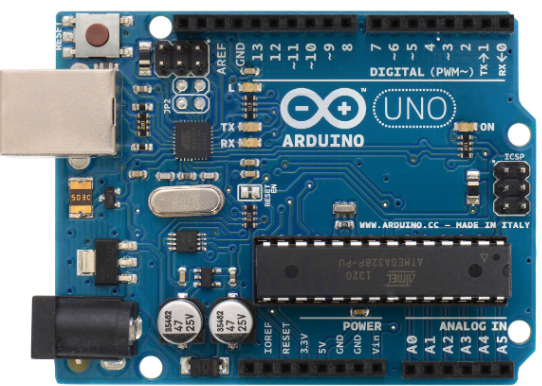
The Arduino UNO is a microcontroller board based on the ATmega328P. It is widely used for building digital devices and interactive objects that can sense and control physical devices. The board features 14 digital input/output pins, 6 analog inputs, a 16 MHz quartz crystal, a USB connection, a power jack, an ICSP header, and a reset button. It is an essential tool for hobbyists, educators, and professionals in the field of electronics and embedded systems.
Explore Projects Built with Arduino UNO
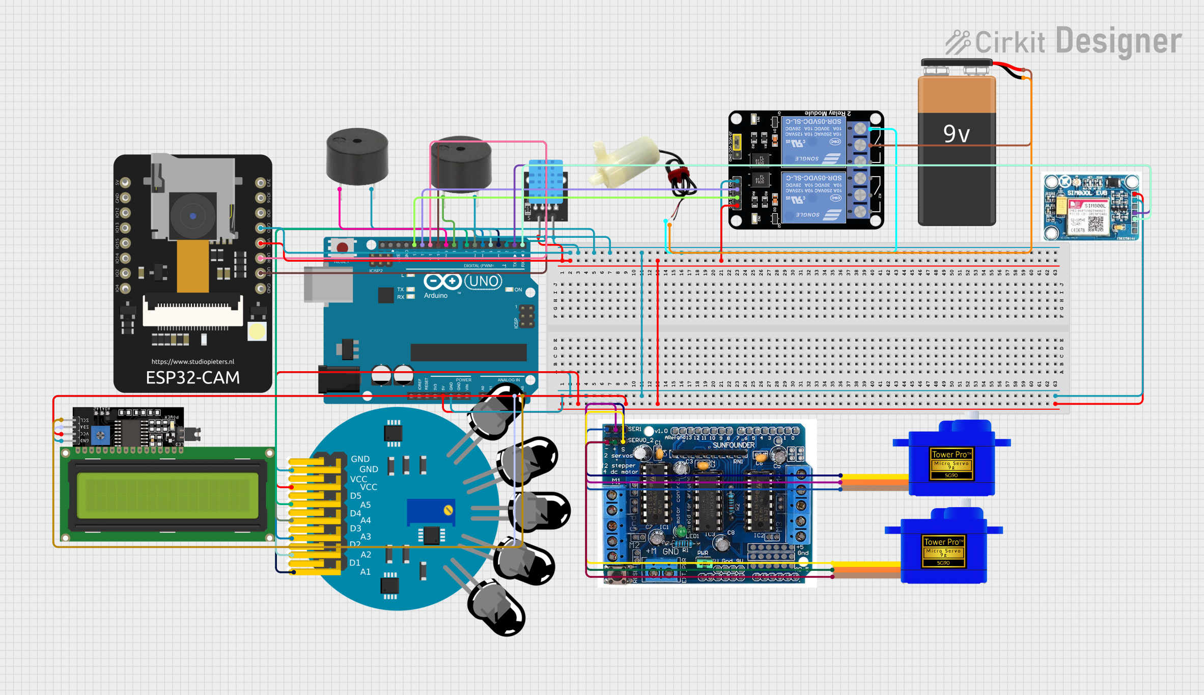
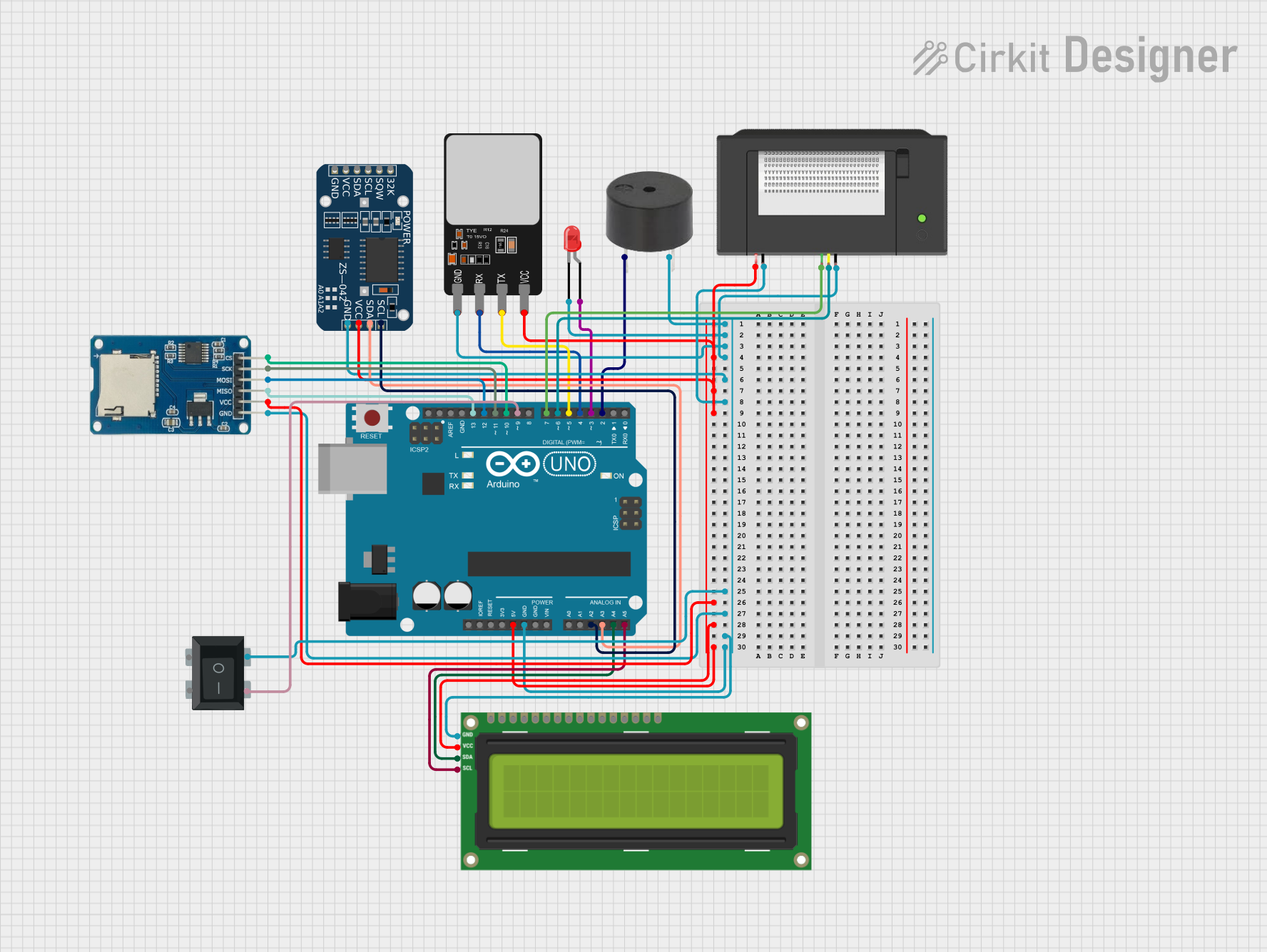
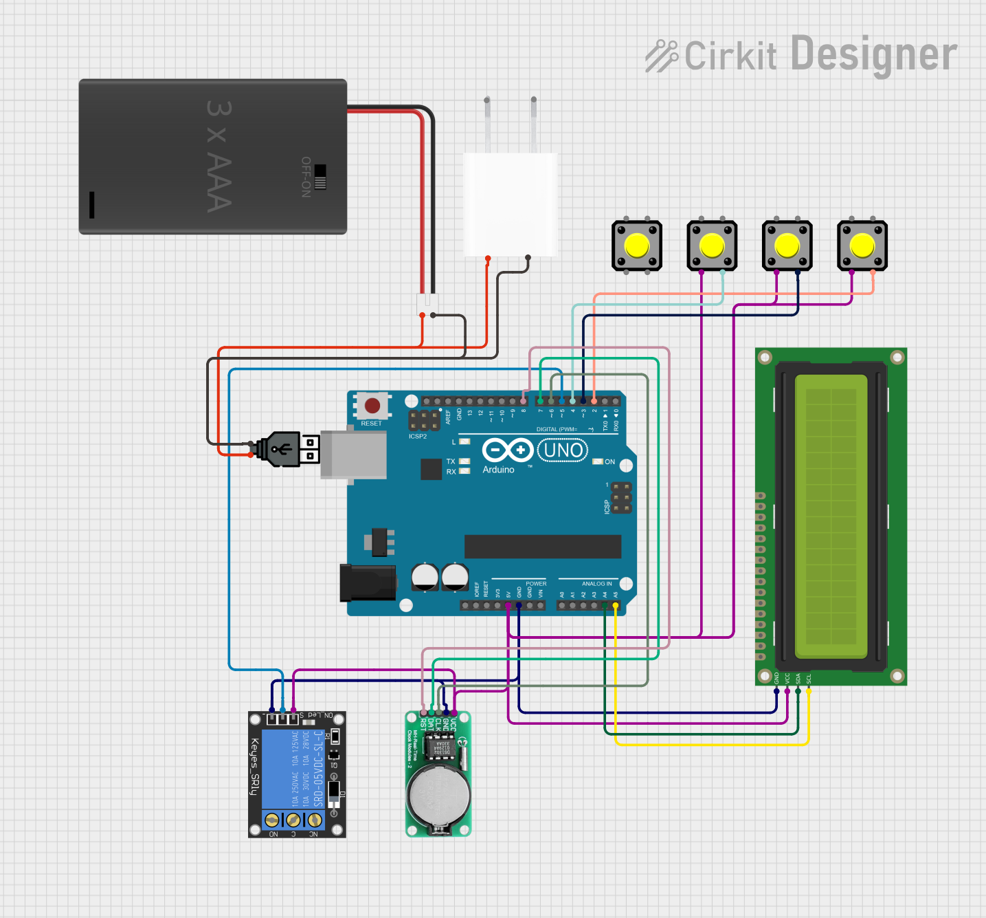
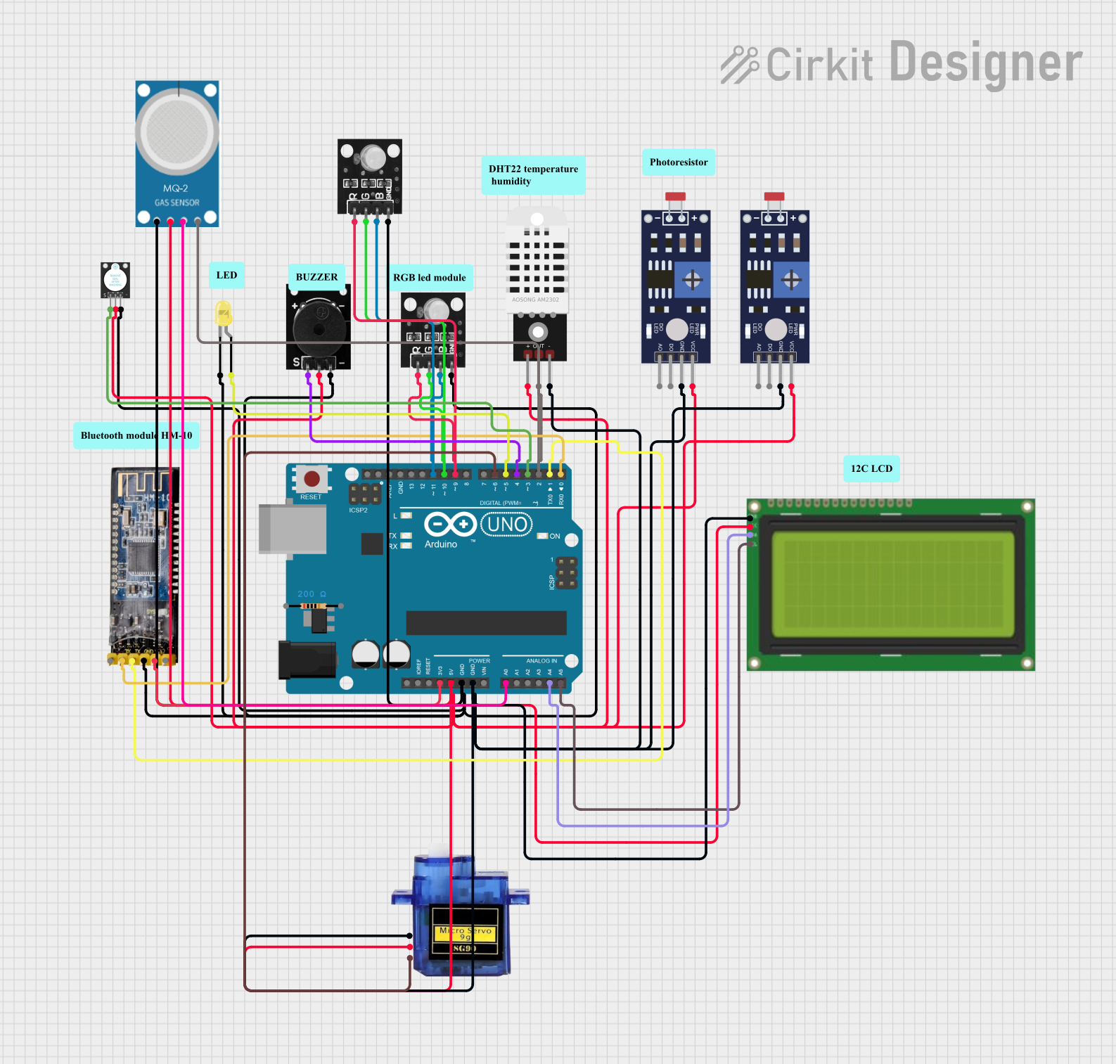
Explore Projects Built with Arduino UNO
Common Applications and Use Cases
- Prototyping: Ideal for rapid prototyping of electronic projects.
- Education: Widely used in educational settings to teach electronics and programming.
- Home Automation: Can be used to control home appliances and systems.
- Robotics: Frequently used in robotics projects for controlling motors and sensors.
- IoT Projects: Acts as a central unit for Internet of Things (IoT) applications.
Technical Specifications
Key Technical Details
| Specification | Value |
|---|---|
| Microcontroller | ATmega328P |
| Operating Voltage | 5V |
| Input Voltage | 7-12V |
| Digital I/O Pins | 14 (6 PWM output) |
| Analog Input Pins | 6 |
| DC Current per I/O Pin | 20 mA |
| Flash Memory | 32 KB (ATmega328P) |
| SRAM | 2 KB (ATmega328P) |
| EEPROM | 1 KB (ATmega328P) |
| Clock Speed | 16 MHz |
Pin Configuration and Descriptions
| Pin Number | Pin Name | Description |
|---|---|---|
| 1-14 | D0-D13 | Digital I/O pins |
| 15-20 | A0-A5 | Analog input pins |
| 21 | GND | Ground |
| 22 | 5V | 5V output |
| 23 | 3.3V | 3.3V output |
| 24 | VIN | Input voltage to the Arduino board |
| 25 | RESET | Reset pin |
| 26 | IOREF | Provides the voltage reference for the I/O pins |
| 27 | AREF | Reference voltage for the analog inputs |
Usage Instructions
How to Use the Component in a Circuit
Powering the Arduino UNO:
- Connect the board to your computer using a USB cable for power and programming.
- Alternatively, use an external power supply (7-12V) connected to the VIN pin or the power jack.
Connecting Digital I/O:
- Use digital pins (D0-D13) for digital input/output operations.
- For PWM output, use pins D3, D5, D6, D9, D10, and D11.
Connecting Analog Inputs:
- Use analog pins (A0-A5) to read analog signals from sensors.
Programming the Arduino UNO:
- Open the Arduino IDE on your computer.
- Select the correct board and port from the Tools menu.
- Write your code and upload it to the board.
Important Considerations and Best Practices
- Avoid Overloading Pins: Ensure that the current drawn from any I/O pin does not exceed 20 mA.
- Use Proper Power Supply: Use a regulated power supply to avoid damaging the board.
- Debounce Buttons: When using buttons, implement debouncing in your code to avoid false triggers.
- Use Pull-up/Pull-down Resistors: For stable digital input readings, use pull-up or pull-down resistors.
Example Code
Here is an example code to blink an LED connected to pin 13:
// This example code will blink an LED connected to pin 13 of the Arduino UNO

void setup() {
  pinMode(13, OUTPUT); // Set pin 13 as an output
}

void loop() {
  digitalWrite(13, HIGH); // Turn the LED on
  delay(1000);            // Wait for one second
  digitalWrite(13, LOW);  // Turn the LED off
  delay(1000);            // Wait for one second
}
Troubleshooting and FAQs
Common Issues Users Might Face
Board Not Recognized by Computer:
- Ensure the USB cable is properly connected.
- Check if the correct board and port are selected in the Arduino IDE.
Upload Error:
- Verify that no other program is using the COM port.
- Press the reset button on the board before uploading.
Unstable Readings from Sensors:
- Use proper grounding and shielding for analog sensors.
- Implement software filtering techniques.
Solutions and Tips for Troubleshooting
- Check Connections: Ensure all connections are secure and correct.
- Update Drivers: Make sure you have the latest drivers installed for the Arduino board.
- Use Serial Monitor: Utilize the Serial Monitor in the Arduino IDE for debugging and monitoring sensor data.
By following this documentation, users can effectively utilize the Arduino UNO for a wide range of applications, from simple LED blinking to complex IoT projects.