How to Use Itrón Cyble Sensor V2: Examples, Pinouts, and Specs
Introduction
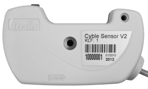
The Itrón Cyble Sensor V2 is an advanced electronic component designed for smart metering solutions. It is capable of accurately measuring and transmitting utility usage data, including water, gas, and electricity consumption. This sensor is widely used in residential, commercial, and industrial applications to facilitate efficient resource management and billing processes.
Explore Projects Built with Itrón Cyble Sensor V2
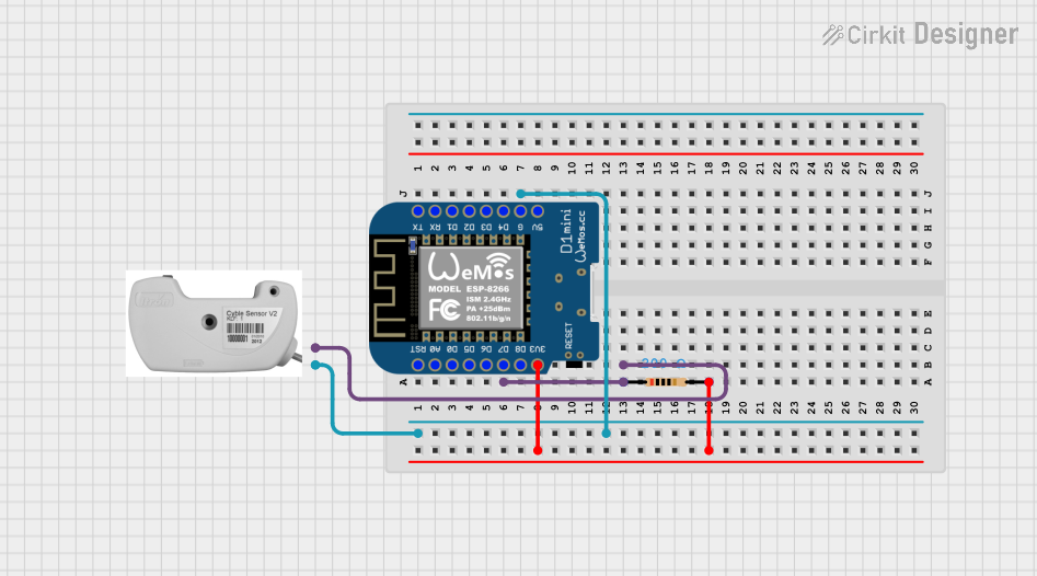


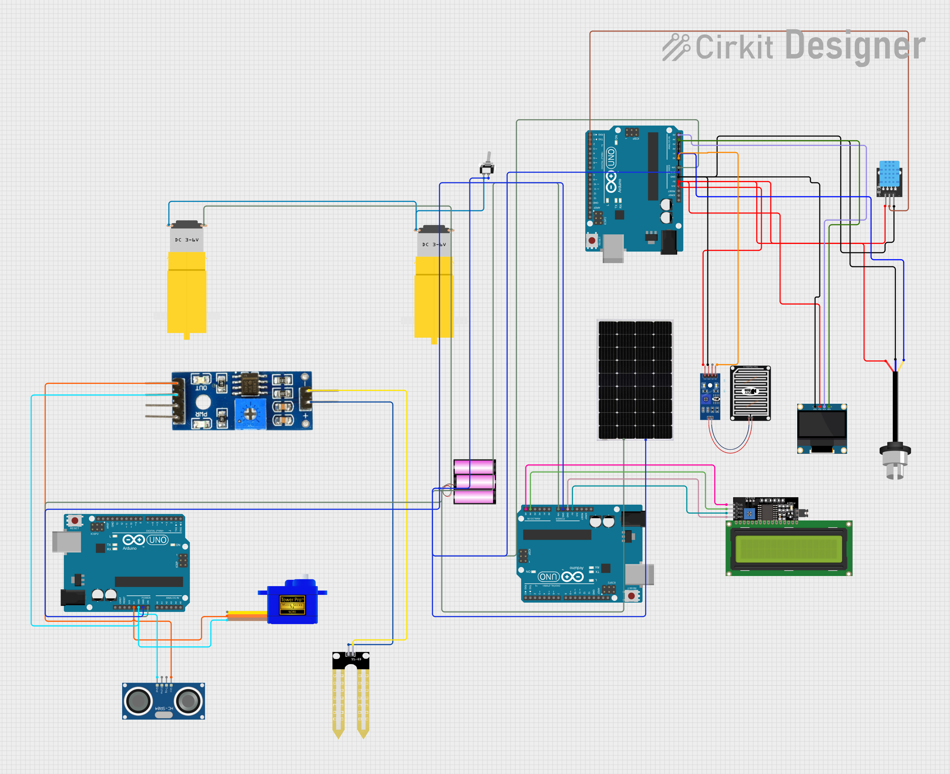
Explore Projects Built with Itrón Cyble Sensor V2
Common Applications and Use Cases
- Smart water meters for residential and commercial buildings
- Gas consumption monitoring in utility management systems
- Electricity usage tracking for energy-saving initiatives
- Remote meter reading in automated meter reading (AMR) systems
- Data collection for advanced metering infrastructure (AMI)
Technical Specifications
Key Technical Details
- Operating Voltage: 3.3V to 5V DC
- Operating Current: Typically 10 mA (active), 1 µA (sleep mode)
- Communication Interface: Pulse output, compatible with various communication modules (e.g., RF, M-Bus)
- Measurement Accuracy: Class B (in accordance with OIML R49)
- Operating Temperature Range: -10°C to +50°C
- Enclosure Rating: IP68 (waterproof and dustproof)
Pin Configuration and Descriptions
| Pin Number | Name | Description |
|---|---|---|
| 1 | VCC | Power supply input (3.3V to 5V DC) |
| 2 | GND | Ground connection |
| 3 | OUT | Pulse output signal |
| 4 | NC | Not connected (reserved for future use) |
Usage Instructions
How to Use the Component in a Circuit
- Power Supply Connection: Connect the VCC pin to a 3.3V or 5V power supply and the GND pin to the common ground in your circuit.
- Output Signal Connection: Connect the OUT pin to a digital input pin on your microcontroller or data logger to capture the pulse output.
- Mounting: Secure the sensor in place according to the manufacturer's guidelines to ensure accurate readings.
Important Considerations and Best Practices
- Ensure that the power supply voltage does not exceed the specified maximum to prevent damage to the sensor.
- Use a pull-up resistor on the OUT pin if your microcontroller does not have an internal pull-up feature.
- Avoid exposing the sensor to temperatures outside the specified operating range.
- Protect the sensor from mechanical shocks and vibrations that could affect its accuracy.
Troubleshooting and FAQs
Common Issues Users Might Face
- No Output Signal: Verify that the power supply is connected correctly and within the specified voltage range. Check the wiring to the microcontroller and ensure the OUT pin is correctly connected.
- Inaccurate Readings: Ensure that the sensor is mounted securely and that there are no vibrations or external factors affecting its operation. Calibrate the sensor if necessary.
Solutions and Tips for Troubleshooting
- If the sensor is not responding, reset the power supply and check all connections.
- For intermittent signal issues, inspect the cable for any damage or loose connections.
- Consult the manufacturer's technical support for calibration procedures or if the problem persists.
Example Code for Arduino UNO
// Define the digital pin connected to the sensor's output
const int sensorPin = 2;

// Variable to store the pulse count
volatile unsigned int pulseCount = 0;

// Interrupt service routine for handling the pulse signal
void ISR_pulse() {
  pulseCount++;
}

void setup() {
  // Initialize the serial communication
  Serial.begin(9600);

  // Set the sensor pin as an input
  pinMode(sensorPin, INPUT_PULLUP);

  // Attach the interrupt to the sensor pin
  attachInterrupt(digitalPinToInterrupt(sensorPin), ISR_pulse, RISING);
}

void loop() {
  // Disable interrupts to read the pulseCount safely
  noInterrupts();
  unsigned int count = pulseCount;
  pulseCount = 0;
  interrupts();

  // Print the pulse count to the serial monitor
  Serial.print("Pulse Count: ");
  Serial.println(count);

  // Add a delay for readability (adjust as needed)
  delay(1000);
}
Note: The example code provided is for demonstration purposes and assumes the use of an Arduino UNO. The interrupt service routine ISR_pulse is triggered on the rising edge of the pulse signal from the Cyble Sensor V2. The pulseCount variable is incremented with each pulse, representing the consumption data. Adjust the code as necessary to match the specific requirements of your application.
For further assistance or more complex integration scenarios, please refer to the manufacturer's detailed technical manuals or contact their support team.