
How to Use 18650 Battery Charger Board - 2.1A 4.2V 18650 Charge/ Discharge/ protection/ indicator module: Examples, Pinouts, and Specs
 Design with 18650 Battery Charger Board - 2.1A 4.2V 18650 Charge/ Discharge/ protection/ indicator module in Cirkit Designer
Introduction
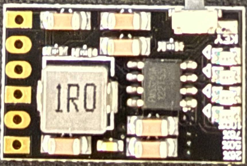
The 18650 Battery Charger Board (Manufacturer: epartners, Part ID: vc1011) is a versatile module designed for charging and discharging 18650 lithium-ion batteries. It features a maximum output current of 2.1A and a charging voltage of 4.2V. The module is equipped with built-in protection circuits to safeguard against overcharging, over-discharging, and short circuits. Additionally, it includes indicator LEDs to display the charging and operational status of the battery.
Explore Projects Built with 18650 Battery Charger Board - 2.1A 4.2V 18650 Charge/ Discharge/ protection/ indicator module
 Open Project in Cirkit Designer
 Open Project in Cirkit Designer
 Open Project in Cirkit Designer
 Open Project in Cirkit Designer
Explore Projects Built with 18650 Battery Charger Board - 2.1A 4.2V 18650 Charge/ Discharge/ protection/ indicator module
Open Project in Cirkit DesignerOpen Project in Cirkit DesignerOpen Project in Cirkit DesignerOpen Project in Cirkit DesignerCommon Applications
- Power banks and portable chargers
- DIY electronics projects
- Battery-powered devices
- Solar-powered systems
- Robotics and IoT applications
Technical Specifications
Below are the key technical details of the 18650 Battery Charger Board:
| Parameter | Value |
|---|---|
| Input Voltage | 5V (via micro-USB or solder pads) |
| Charging Voltage | 4.2V ± 1% |
| Maximum Charging Current | 2.1A |
| Discharge Voltage Range | 2.5V - 4.2V |
| Maximum Discharge Current | 2.1A |
| Protection Features | Overcharge, Over-discharge, Short Circuit |
| Indicator LEDs | Charging (Red), Fully Charged (Blue) |
| Dimensions | 25mm x 19mm x 5mm |
Pin Configuration and Descriptions
The module has several input/output connections for integration into circuits. Below is the pin configuration:
| Pin Name | Type | Description |
|---|---|---|
B+ |
Battery Input | Positive terminal of the 18650 battery |
B- |
Battery Input | Negative terminal of the 18650 battery |
OUT+ |
Output | Positive terminal for load connection |
OUT- |
Output | Negative terminal for load connection |
5V |
Input | 5V input for charging (via micro-USB or solder pads) |
Usage Instructions
How to Use the Component in a Circuit
Connect the Battery:
- Solder the positive terminal of the 18650 battery to the
B+pin. - Solder the negative terminal of the 18650 battery to the
B-pin. - Ensure the battery is not connected in reverse to avoid damage.
- Solder the positive terminal of the 18650 battery to the
Connect the Load:
- Connect the positive terminal of your load to the
OUT+pin. - Connect the negative terminal of your load to the
OUT-pin.
- Connect the positive terminal of your load to the
Power the Module:
- Provide a 5V input to the module via the micro-USB port or the
5Vsolder pads. - The module will automatically begin charging the battery.
- Provide a 5V input to the module via the micro-USB port or the
Monitor the LEDs:
- The red LED indicates that the battery is charging.
- The blue LED indicates that the battery is fully charged.
Important Considerations and Best Practices
- Use only high-quality 18650 lithium-ion batteries to ensure safety and performance.
- Avoid exceeding the maximum input voltage of 5V to prevent damage to the module.
- Ensure proper heat dissipation if the module is used at maximum current (2.1A) for extended periods.
- Do not short-circuit the output terminals (
OUT+andOUT-). - Disconnect the battery if the module is not in use for long periods to prevent over-discharge.
Example: Using with Arduino UNO
The module can be used to power an Arduino UNO. Below is an example of how to connect the module and a simple Arduino sketch to monitor the battery voltage:
Circuit Connection
- Connect the
OUT+pin of the module to theVINpin of the Arduino UNO. - Connect the
OUT-pin of the module to theGNDpin of the Arduino UNO.
Arduino Code
// Simple Arduino sketch to monitor battery voltage
const int batteryPin = A0; // Analog pin connected to battery output
float voltage = 0.0;

void setup() {
  Serial.begin(9600); // Initialize serial communication
  pinMode(batteryPin, INPUT); // Set battery pin as input
}

void loop() {
  int sensorValue = analogRead(batteryPin); // Read analog value
  voltage = sensorValue * (5.0 / 1023.0) * 2;
  // Convert to voltage (assuming a voltage divider is used)

  Serial.print("Battery Voltage: ");
  Serial.print(voltage);
  Serial.println(" V");

  delay(1000); // Wait for 1 second before next reading
}
Note: If the battery voltage exceeds 5V, use a voltage divider to scale it down before connecting to the Arduino analog pin.
Troubleshooting and FAQs
Common Issues and Solutions
Module Not Charging the Battery:
- Ensure the input voltage is 5V and properly connected.
- Verify the battery is connected correctly to the
B+andB-pins. - Check if the battery is damaged or fully discharged below 2.5V.
LEDs Not Lighting Up:
- Confirm the input power source is functioning and delivering 5V.
- Inspect solder joints for loose or improper connections.
Overheating During Operation:
- Ensure the module is not operating beyond its maximum current rating (2.1A).
- Provide adequate ventilation or a heatsink if necessary.
Output Voltage is Zero:
- Verify the battery is charged and connected properly.
- Check for short circuits or damaged components on the module.
FAQs
Q: Can I use this module with batteries other than 18650?
A: This module is specifically designed for 18650 lithium-ion batteries. Using other types of batteries may result in improper charging or damage.
Q: Can I charge multiple 18650 batteries in parallel?
A: Yes, but ensure the batteries are of the same type, capacity, and charge level. Also, ensure the total current does not exceed the module's 2.1A limit.
Q: Is it safe to leave the battery connected to the module indefinitely?
A: Yes, the module includes overcharge protection, but it is recommended to disconnect the battery if not in use for extended periods.
Q: Can I use this module to power high-current devices?
A: The module supports a maximum discharge current of 2.1A. For devices requiring higher currents, use a separate power management circuit.