Cirkit Designer
Your all-in-one circuit design IDE
Home /
Component Documentation
How to Use BMI323: Examples, Pinouts, and Specs
Introduction
The BMI323 is a 3-axis digital accelerometer and gyroscope sensor manufactured by Bosch. It is designed for motion tracking applications, offering high precision measurements of angular velocity and acceleration. This sensor is ideal for use in smartphones, wearables, gaming devices, and other IoT applications requiring accurate motion detection and orientation tracking.
Explore Projects Built with BMI323
ESP32 and INA3221-Based Smart Power Monitoring System with Bluetooth and Environmental Sensing
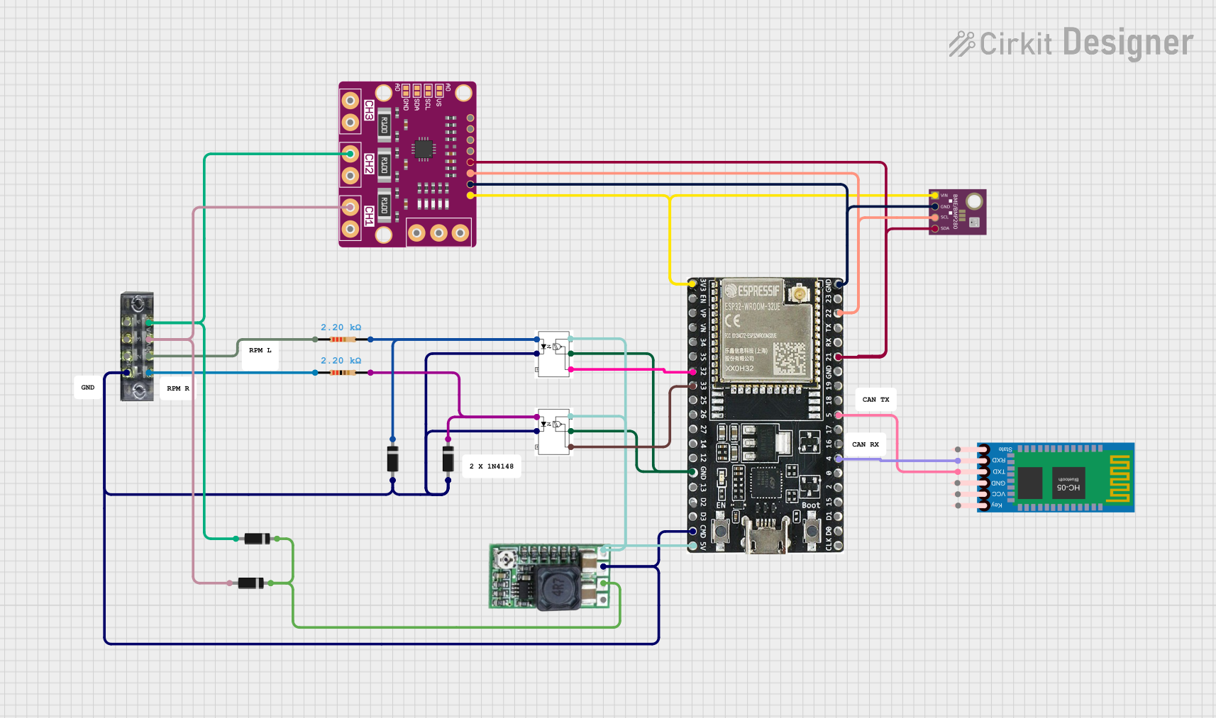
This circuit is a sensor monitoring and communication system that uses an ESP32 microcontroller to read data from a BME/BMP280 environmental sensor and an INA3221 power monitor. The ESP32 communicates with the sensors via I2C and transmits data wirelessly using an HC-05 Bluetooth module. Additionally, the circuit includes optocouplers and diodes for signal isolation and protection.
ESP32-CAM Smart Security System with PIR Sensor and BMP280, Battery-Powered and Wi-Fi Controlled
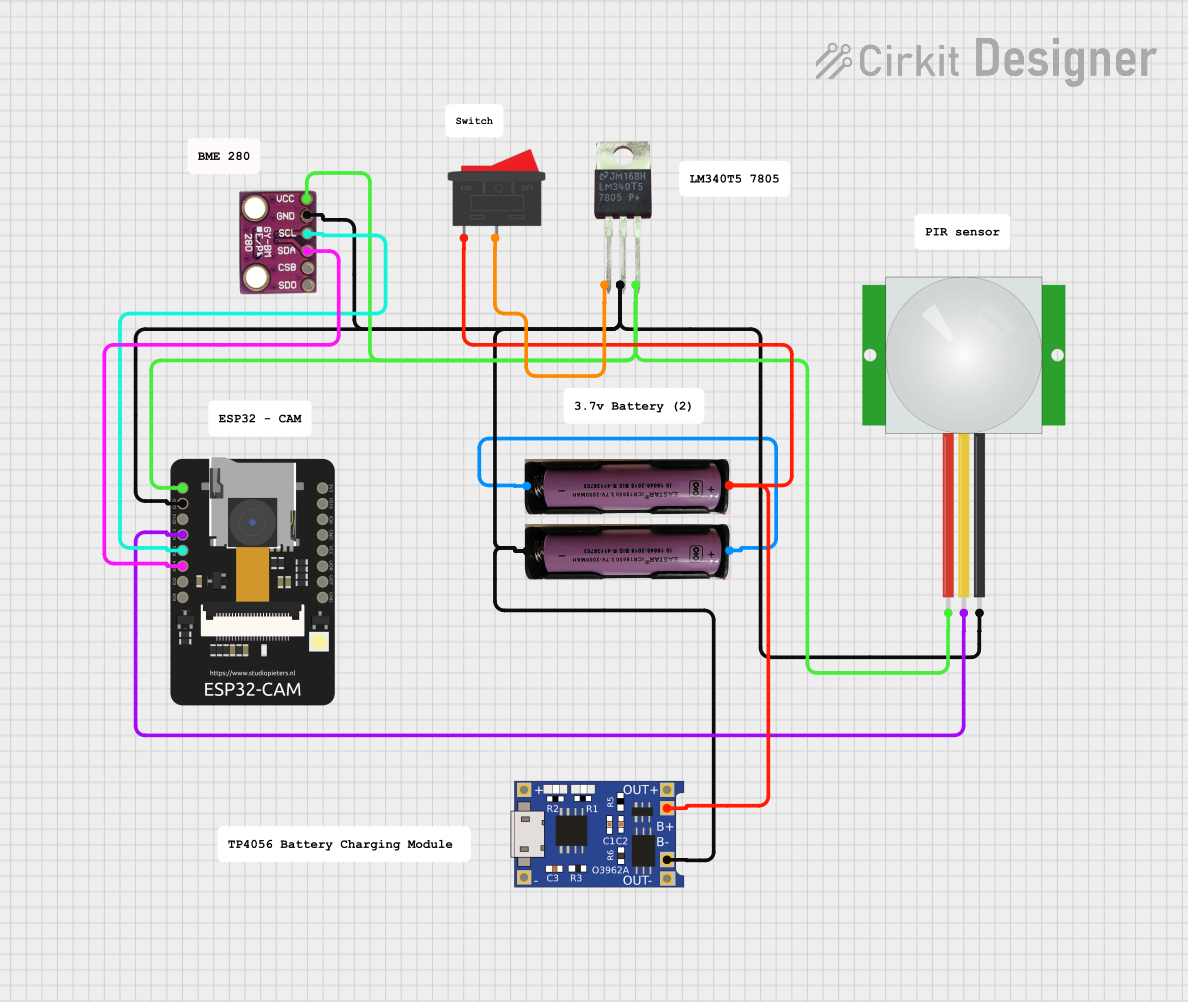
This circuit is a wireless surveillance system using an ESP32-CAM module, a PIR motion sensor, and a BMP280 sensor. The ESP32-CAM captures images and sends them via Telegram when motion is detected by the PIR sensor, while the BMP280 provides environmental data. The system is powered by a 3.7V battery, regulated to 5V using an LM340T5 7805 voltage regulator, and includes a TP4056 for battery charging.
ESP32-Based Environmental Monitoring System with Solar Charging
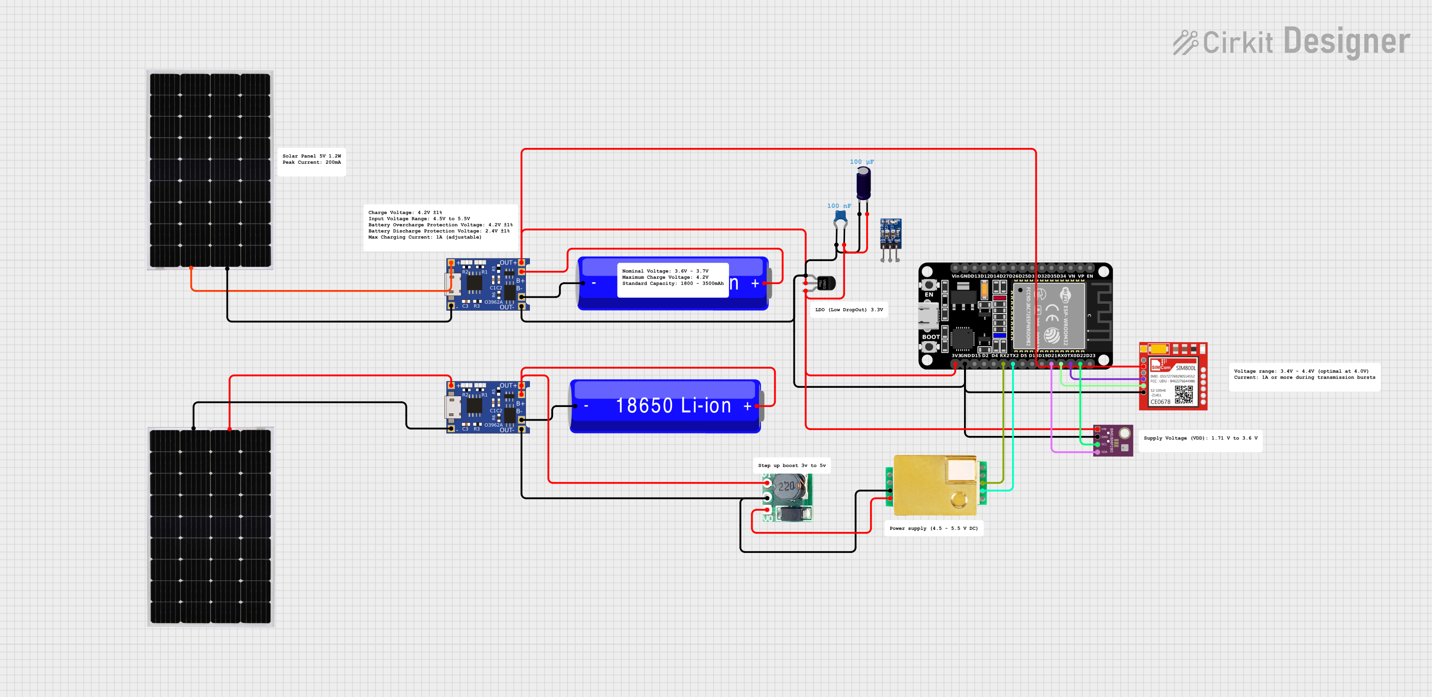
This circuit features an ESP32 microcontroller interfaced with a BME/BMP280 sensor for environmental monitoring and an MH-Z19B sensor for CO2 measurement, both communicating via I2C (SCL, SDA) and serial (TX, RX) connections respectively. It includes a SIM800L module for GSM communication, connected to the ESP32 via serial (TXD, RXD). Power management is handled by two TP4056 modules for charging 18650 Li-ion batteries via solar panels, with a step-up boost converter to provide consistent voltage to the MH-Z19B, and voltage regulation for the SIM800L. Decoupling capacitors are used to stabilize the power supply to the BME/BMP280 and ESP32.
Solar-Powered Environmental Monitoring System with ESP32 and Cellular Connectivity
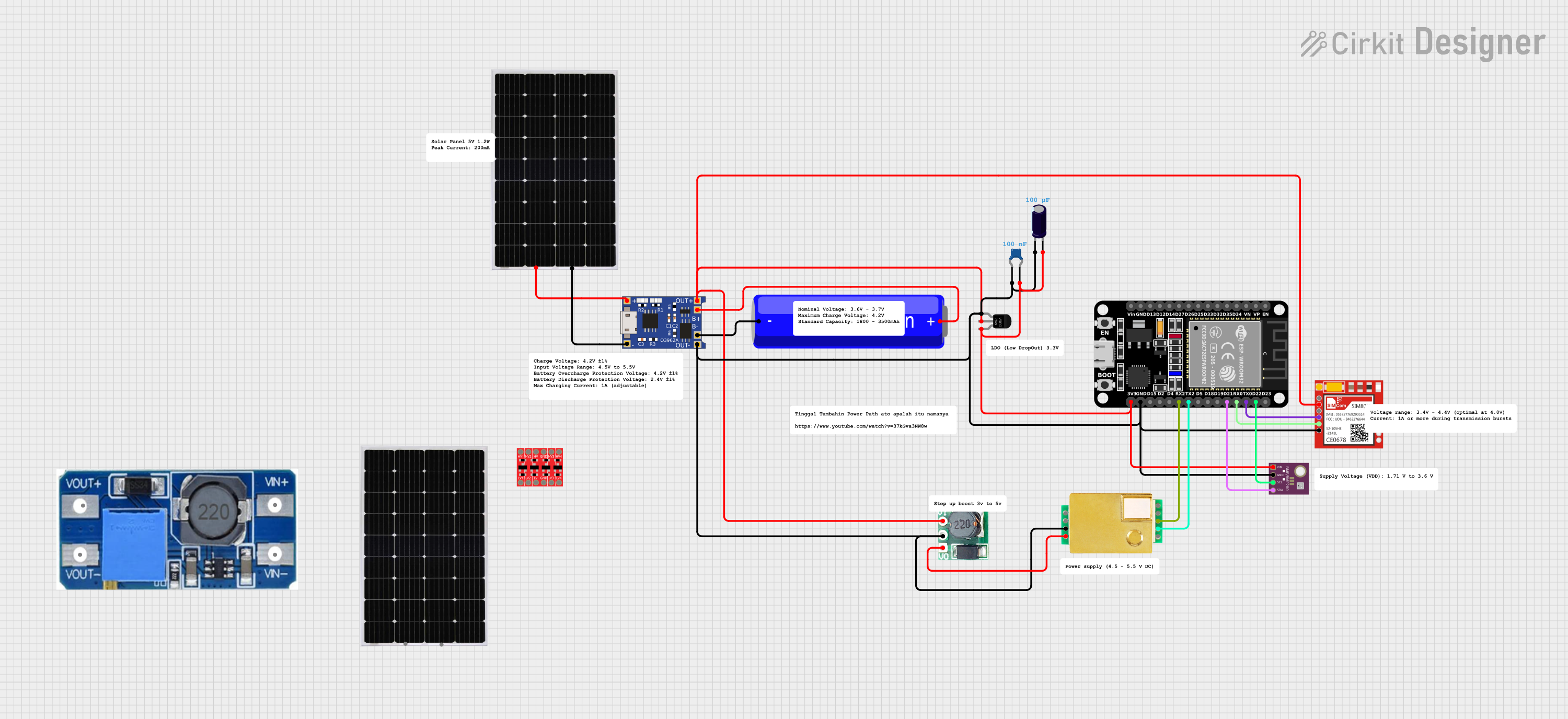
This circuit features an ESP32 microcontroller interfaced with a BME/BMP280 sensor for environmental data and an MH-Z19B sensor for CO2 measurement, both communicating via I2C (SCL, SDA) and serial (TX, RX) connections respectively. It includes a TP4056 module for charging an 18650 Li-ion battery from a solar panel, with a step-up boost converter to provide stable voltage to the MH-Z19B sensor and a voltage regulator for the SIM800L GSM module. The capacitors are likely used for power supply filtering or decoupling.
Explore Projects Built with BMI323
ESP32 and INA3221-Based Smart Power Monitoring System with Bluetooth and Environmental Sensing
This circuit is a sensor monitoring and communication system that uses an ESP32 microcontroller to read data from a BME/BMP280 environmental sensor and an INA3221 power monitor. The ESP32 communicates with the sensors via I2C and transmits data wirelessly using an HC-05 Bluetooth module. Additionally, the circuit includes optocouplers and diodes for signal isolation and protection.
ESP32-CAM Smart Security System with PIR Sensor and BMP280, Battery-Powered and Wi-Fi Controlled
This circuit is a wireless surveillance system using an ESP32-CAM module, a PIR motion sensor, and a BMP280 sensor. The ESP32-CAM captures images and sends them via Telegram when motion is detected by the PIR sensor, while the BMP280 provides environmental data. The system is powered by a 3.7V battery, regulated to 5V using an LM340T5 7805 voltage regulator, and includes a TP4056 for battery charging.
ESP32-Based Environmental Monitoring System with Solar Charging
This circuit features an ESP32 microcontroller interfaced with a BME/BMP280 sensor for environmental monitoring and an MH-Z19B sensor for CO2 measurement, both communicating via I2C (SCL, SDA) and serial (TX, RX) connections respectively. It includes a SIM800L module for GSM communication, connected to the ESP32 via serial (TXD, RXD). Power management is handled by two TP4056 modules for charging 18650 Li-ion batteries via solar panels, with a step-up boost converter to provide consistent voltage to the MH-Z19B, and voltage regulation for the SIM800L. Decoupling capacitors are used to stabilize the power supply to the BME/BMP280 and ESP32.
Solar-Powered Environmental Monitoring System with ESP32 and Cellular Connectivity
This circuit features an ESP32 microcontroller interfaced with a BME/BMP280 sensor for environmental data and an MH-Z19B sensor for CO2 measurement, both communicating via I2C (SCL, SDA) and serial (TX, RX) connections respectively. It includes a TP4056 module for charging an 18650 Li-ion battery from a solar panel, with a step-up boost converter to provide stable voltage to the MH-Z19B sensor and a voltage regulator for the SIM800L GSM module. The capacitors are likely used for power supply filtering or decoupling.
Common Applications
- Motion tracking in smartphones and tablets
- Fitness and health monitoring in wearables
- Gesture recognition in gaming devices
- Robotics and drone navigation
- Industrial IoT for vibration and motion analysis
Technical Specifications
The BMI323 combines a 3-axis accelerometer and a 3-axis gyroscope in a compact package. Below are the key technical details:
Key Specifications
| Parameter | Value |
|---|---|
| Supply Voltage (VDD) | 1.71V to 3.6V |
| I/O Voltage (VDDIO) | 1.2V to 3.6V |
| Power Consumption | 850 µA (typical, full operation) |
| Measurement Range (Accel) | ±2g, ±4g, ±8g, ±16g |
| Measurement Range (Gyro) | ±125°/s, ±250°/s, ±500°/s, ±1000°/s, ±2000°/s |
| Output Data Rate (ODR) | Up to 6.4 kHz |
| Interface | I²C, SPI |
| Operating Temperature | -40°C to +85°C |
| Package Size | 2.5 mm x 3.0 mm x 0.83 mm |
Pin Configuration
The BMI323 is available in a 12-pin LGA package. Below is the pin configuration:
| Pin Number | Pin Name | Description |
|---|---|---|
| 1 | VDD | Power supply |
| 2 | VDDIO | I/O voltage supply |
| 3 | GND | Ground |
| 4 | CS | Chip select (SPI) / I²C address select |
| 5 | SCL | Serial clock (I²C) / SPI clock |
| 6 | SDA | Serial data (I²C) / SPI data input |
| 7 | SDO | SPI data output |
| 8 | INT1 | Interrupt 1 output |
| 9 | INT2 | Interrupt 2 output |
| 10 | NC | Not connected |
| 11 | NC | Not connected |
| 12 | GND | Ground |
Usage Instructions
How to Use the BMI323 in a Circuit
- Power Supply: Connect the VDD pin to a 1.71V to 3.6V power source and the VDDIO pin to the desired I/O voltage (1.2V to 3.6V). Connect all GND pins to the ground.
- Communication Interface: Choose between I²C or SPI for communication:
- For I²C, connect the SCL and SDA pins to the corresponding I²C lines on your microcontroller. Use pull-up resistors (typically 4.7 kΩ) on both lines.
- For SPI, connect the CS, SCL, SDA, and SDO pins to the corresponding SPI lines on your microcontroller.
- Interrupts: Use the INT1 and INT2 pins to configure and handle interrupts for motion detection or other events.
- Initialization: Configure the sensor's registers via the chosen communication interface to set the desired measurement range, output data rate, and other parameters.
Important Considerations
- Bypass Unused Pins: Leave NC pins unconnected.
- Decoupling Capacitors: Place a 0.1 µF decoupling capacitor close to the VDD and VDDIO pins to reduce noise.
- I²C Address: The I²C address of the BMI323 is determined by the CS pin. Pulling CS low sets the address to 0x68, while pulling it high sets it to 0x69.
- Orientation: Ensure the sensor is mounted correctly to align with the desired axes of measurement.
Example Code for Arduino UNO
Below is an example of how to interface the BMI323 with an Arduino UNO using I²C:
#include <Wire.h>

#define BMI323_I2C_ADDRESS 0x68 // Default I²C address when CS is low

// BMI323 register addresses
#define BMI323_CHIP_ID_REG 0x00
#define BMI323_ACCEL_X_LSB 0x12

void setup() {
  Wire.begin(); // Initialize I²C communication
  Serial.begin(9600); // Initialize serial communication for debugging

  // Check BMI323 connection
  Wire.beginTransmission(BMI323_I2C_ADDRESS);
  Wire.write(BMI323_CHIP_ID_REG); // Request chip ID register
  Wire.endTransmission();
  Wire.requestFrom(BMI323_I2C_ADDRESS, 1);

  if (Wire.available()) {
    uint8_t chipID = Wire.read();
    if (chipID == 0x33) { // Expected chip ID for BMI323
      Serial.println("BMI323 detected!");
    } else {
      Serial.println("BMI323 not detected. Check connections.");
    }
  }
}

void loop() {
  // Read accelerometer X-axis data
  Wire.beginTransmission(BMI323_I2C_ADDRESS);
  Wire.write(BMI323_ACCEL_X_LSB); // Request X-axis LSB register
  Wire.endTransmission();
  Wire.requestFrom(BMI323_I2C_ADDRESS, 2); // Read 2 bytes (LSB + MSB)

  if (Wire.available() == 2) {
    int16_t accelX = Wire.read(); // Read LSB
    accelX |= (Wire.read() << 8); // Read MSB and combine
    Serial.print("Accel X: ");
    Serial.println(accelX);
  }

  delay(100); // Delay for readability
}
Troubleshooting and FAQs
Common Issues
Sensor Not Detected:
- Ensure the I²C address matches the configuration of the CS pin.
- Check the wiring and ensure pull-up resistors are used on the I²C lines.
- Verify the power supply voltage is within the specified range.
Incorrect Readings:
- Confirm the sensor is properly mounted and aligned with the desired axes.
- Check the configuration of the measurement range and output data rate.
No Interrupts Triggered:
- Verify the interrupt pins (INT1/INT2) are properly connected to the microcontroller.
- Ensure the interrupt registers are correctly configured.
Tips for Troubleshooting
- Use an oscilloscope or logic analyzer to verify I²C or SPI communication.
- Check for noise or instability in the power supply and add additional filtering if needed.
- Refer to the BMI323 datasheet for detailed register descriptions and configuration options.